


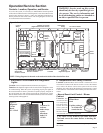

Page 10
15. Dirty Filter Switch
Location: Switch is located in the
main electrical box (See Figure 7);
sensor tubes run to either side of
the filter rack; indicator light is on
the remote console.
Function: The dirty filter
switch is a pressure switch that
activates an indicator light on the
remote console when the filters
need cleaned or replaced (See Ser-
vice Section, Paragraph 2). This
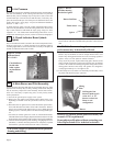
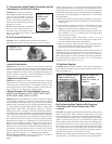
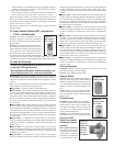
Figure 27 - Dirty Filter
Pressure Switch, P/N
105507
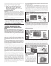
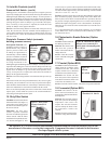
Figure 28 - Photoelectric Smoke
Detector (cover removed), P/N
159553, used with sampling tube,
P/N 159714
switch is only on systems with an optional console that includes a dirty
filter light. The pressure switch is set during installation so that the light
will be activated at approximately 50% filter blockage. Contacts should
close at .17 to 5.0" w.c. ± .05" w.c.
Service: Clean the sensor tubes. If the dirty filter indicator system still
does not function properly, check the setting of the switch. With clean
filters in place, blower doors closed, and blower in operation, decrease
the pressure setting by adjusting the set screw on the switch clockwise
until the filter light is energized or screw is bottomed out. At that point,
adjust the set screw three full turns counterclockwise or until the screw
is top ended.
If it is determined that the switch needs replacing, use an identical
switch. When a new switch is installed, it must be manually set; follow
the instructions above.
16. Photoelectric Smoke Detector (Option
SA1)
Location: Field-mounted in
the discharge ductwork.
Function: The detector will
shut down the system if
smoke is detected in the dis-
charge ductwork.
Service: Clean the external
surface. Check the wiring and
connections.
17. Firestat (Option BD5)
Location: Field-mounted on the dis-
charge ductwork so that the sensor
extends into the duct. This control
requires manual reset so should be
mounted in an accessible location.
Function: The firestat will shut
down the system if the temperature
in the ductwork reaches 200°F. The
switch must be manually reset.
Service: Clean the external surface. Check the wiring and connections.
18. Freezestat (Option BE2)
Location: The control is in the
blower section electrical box; the
sensing bulb is field-mounted in the
discharge duct.
Function: The freezestat will shut
down the system if the discharge
temperature falls below the
setpoint. The switch is automatic
and will startup the heater when
the temperature reaches the
setpoint.
Service: Clean the external surface.
Check the wiring and connections.
Photohelic Pressure Switch (automatic
building pressure sensor)
Description/Function: The
photohelic pressure switch is a
phototransister relay operated
positive pressure switch used
in makeup air applications to
automatically control building
pressure. It maintains a selected
positive pressure setpoint by
changing the amount of outside
air being introduced to the
building through a modulating outside air damper. As more pressure is
required in the building, the switch activates the damper motor driving
the outside air damper towards the full open position (causing the
bypass return air damper to go toward the closed position). Con-
versely, as less pressure is required, the switch drives the outside air
damper in the opposite direction.
Service: Clean the tubing and the screened ends of the pressure tap
vents.
If the interior of the switch is protected from dust, dirt, corrosive gases
and fluids, years of trouble-free service may be expected. Zero adjust-
ment should be checked and reset occasionally to maintain accuracy;
follow the manufacturer's instructions included with the switch.
There are no field-repairable parts in this switch. If the switch should
require repair, contact either the system or the switch manufacturer
concerning switch replacement or repair.
14. Inlet Air Controls (cont'd)
Pressure Null Switch (cont'd)
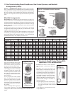
Figure 29 -
Firestat,
P/N 42782
Figure 30 - Freezestat
Controller, P/N 126170
REFERENCE: For service and troubleshooting information on the electrical controls, refer to the
manufacturer's literature covering that component. Component literature is included in the literature
envelope shipped with the system.
Refer to Paragraph 19 for unit troubleshooting.
Figure 26 -
Photohelic
Pressure
Sensor,
P/N
159893
building pressure. It maintains a selected positive or negative pressure
setpoint by changing the amount of outside air being introduced to the
building through modulating outside air damper. As more pressure is
required in the building, the pressure null switch activates the damper
motor driving the outside air damper towards the full open position
(causing the bypass return air damper to go toward the closed posi-
tion). Conversely, as less pressure is required, the switch drives the
outside air damper in the opposite direction.
Service: Clean the tubing and the screened ends of the pressure tap
vents. Be sure that the switch is installed with the diaphragm in a
vertical plane and that the pressure taps are sheltered from the wind.
For further service, follow the manufacturer's instructions included
with the switch.