


Page 8
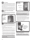
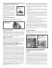
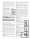
12. Outside Air Cutoff Control (Option BN2;
required on C.G.A.-certified units)
Location: The control is in the electrical
box (See Figure 7.); the sensor is in the air
inlet.
Function: After sensing pilot flame, the
burner ignites at its lowest input rate. The
"amount of heat" required to reach the de-
sired discharge temperature also depends on
the temperature of the incoming outside air.
The outside air control is factory set at 60°F
(adjustable 25-250°F). The burner reacts
differently depending on the entering air tem-
perature and the setting on the outside air
control. The burner --
• may not ignite (pilot valve will not open);
If the actual temperature of the outside
air is above the setpoint on the outside air control, the burner will
not ignite.
• may modulate to satisfy discharge setting;
• may shutdown; or
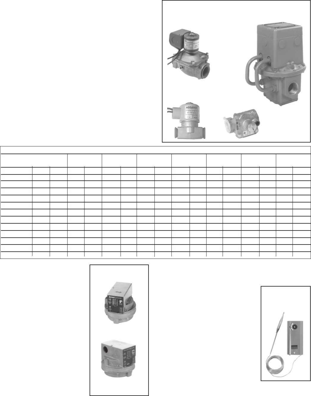
Figure 21 -
Outside Air
Cutoff Control
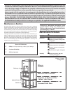
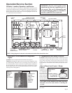
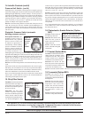
Figure 19 - Gas Manifold Control Components
Solenoid Valve
Manifold Arrangements
Description: The manifold is the gas train from the gas supply con-
nection to the burner. The manifold selection ordered determines the
manifold arrangement including all of the gas train components except
the main control valve. Manifold arrangements are available for varying
BTUH ranges and gas controls and include versions that meet FM or
IRI requirements.
In addition to the Maxitrol valve and two solenoid valves, all manifold
arrangements include main gas and pilot gas shut-off cocks, a pilot
regulator, and a pilot solenoid valve.
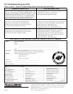
The table below lists the pressure drops through the various types of
manifolds by option designation (BM). To determine the required mini-
mum supply pressure for natural gas, add 5.0" w.c. to the natural gas
manifold pressure drop. For propane gas, add 2.0" w.c.
Modulating/
Regulating
Valve
11. Gas Train Including Direct-Fired Burner, Gas Control Systems, and Manifold
Arrangements (cont'd)
Pilot Valve
Pilot Regulator
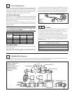
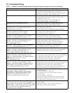
Gas Pressure Switches
If the gas train includes either or both
high and low gas pressure switches,
the switches monitor gas pressure
downstream from the safety valves.
If the gas pressure in a system equipped
with a high gas pressure switch (Op-
tion BP2) exceeds the setpoint, the
switch will open the electrical circuit
to the burner, stopping all gas flow.
The high gas pressure switch is a manu-
ally reset device.
A low gas pressure switch (Option
BP3) will shutoff the gas flow if the
gas pressure drops below the setpoint
of the low pressure switch. The low
gas pressure switch will automatically
reset when the gas pressure rises above
the setpoint.
(NOTE: Both high and low gas pres-
sure switches incorporate a vent limiting device and do not require
venting to the outdoors when used in an application installed indoors.)
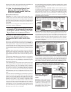
Figure 20 - Gas
Pressure Switches
Low, P/N 93850
(automatic)
High, P/N 93849
(manual reset)
Manifold Pressure Drops (“ w.c.)
Manifold Opt BM62 BM63 BM64 BM65 BM67 BM68 BM53 BM66
Manifold Size 1" 3/4" 1" 1-1/4" 1-1/4" 2" 1-1/4" 2"
MBH Nat Pro Nat Pro Nat Pro Nat Pro Nat Pro Nat Pro Nat Pro Nat Pro
250 .56 .21 .66 .25 .43 .17 .22 .09 .19 .07 .07 .03 .22 .09 .07 .03
500 2.23 .85 2.65 1.01 1.74 .66 .89 .34 .76 .29 .27 .10 .89 .34 .27 .10
750 5.02 1.91 5.96 2.27 3.91 1.49 2.01 .77 1.71 .65 .61 .23 2.01 .77 .61 .23
1000 -- -- -- -- 6.95 2.65 3.58 1.36 3.04 1.16 1.09 .41 3.58 1.36 1.09 .41
1250 -- -- -- -- -- -- 5.59 2.13 4.76 1.81 1.70 .65 5.59 2.13 1.70 .65
1500 -- -- -- -- -- -- 8.05 3.07 6.85 2.61 2.44 .93 8.05 3.07 2.44 .93
1750 -- -- -- -- -- -- 10.96 4.17 9.32 3.55 3.33 1.27 10.96 4.17 3.33 1.27
2000 -- -- -- -- -- -- 14.31 5.45 12.18 4.64 4.34 1.66 14.31 5.45 4.34 1.66
2250 -- -- -- -- -- -- 18.11 6.90 15.41 5.87 5.50 2.09 18.11 6.90 5.50 2.09
2500 -- -- -- -- -- -- 22.36 8.52 19.02 7.25 6.79 2.59 22.36 8.52 6.79 2.59
2750 -- -- -- -- -- -- -- -- -- -- 8.21 3.13 -- -- 8.21 3.13
3000 -- -- -- -- -- -- -- -- -- -- 9.77 3.72 -- -- 9.77 3.72
Service - All Maxitrol Controls: Check all electrical connec-
tions. A qualified service person should refer to the Maxitrol Trouble-
shooting Guides for assistance in identifying problems and determining
the correct solution. None of the Maxitrol controls have field replace-
able parts. All components must be replaced with identical replacement
parts.