


Page 5
Operation/Service Section
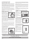
Controls - Location, Operation, and Service
To service this system, it is necessary to understand the normal operation
of the controls and the function of the diagnostic circuit board. Refer to the
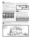
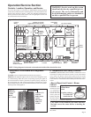
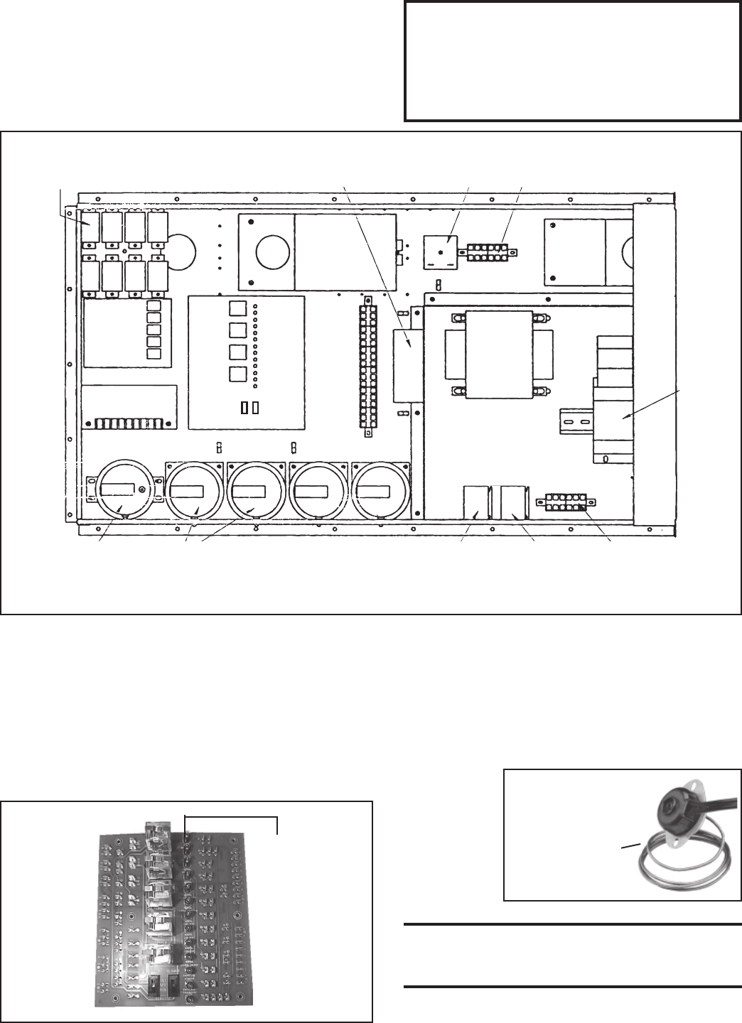
electrical box drawing in Figure 7 and to the individual illustrations to
identify and locate each of the controls. The wiring diagrams for this unit
are located in the main electrical box.
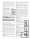
7. Electronic Circuit Board with Diagnostic
Lights
Location: Control Compartment Electrical Box (See Figure 7)
Function: The diagnostic lights on the circuit board are designed to assist
in troubleshooting. When the system is operating properly, the lights on
the circuit board are lit. If the system fails to operate properly, all lights on
the circuit board up to that one that represents the component or system
that has failed will be lit. For more detailed information, refer to the Trouble-
shooting Guide in Paragraph 19.
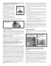
Figure 8 -
Diagnostic
Circuit
Board,
P/N 151263
Column of 13
indicator
bulbs; always
replace
burned out
bulbs, P/N
125189.
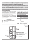
Figure 7 - Control Locations
8. Temperature Limit Safety Controls
Location: 1) Manual Reset Limit Switch is mounted on a 2x4
electrical box located in the blower section. To access the manual
reset, remove the blower section access panel to the left of the
discharge (left when facing the discharge); 2) Emergency Cutoff
Limit Control is in the burner/control cabinet just above the electri-
cal box.
• Manual Reset Limit Control - Blower
Cabinet
Function: The
manual reset limit
is a temperature
activated safety
control. Re-start
of the system can
be done only after
the limit control is
cooled and the reset button is depressed.
CAUTION: If the manual reset limit activates,
find and correct the cause before re-starting the
system.
Service: Failure of the manual reset limit requires replacement of
the control.
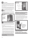
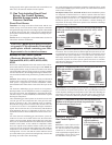
Figure 9 -
Manual Reset
Limit
Capillary tubing is
in a holder that
extends into the
Control
Relays
Outside Air Cutoff
(high ambient limit control)
Time Delay
Relay
24-volt Terminals
Ignition
Module
Maxitrol Amplifier
or Signal Conditioner
Service
Switches
Status Lights
Circuit
Board
24-Volt Terminals
Bypass
Damper
Motor
Return
Air
Damper
Motor
Motor
Starter
Transformer
Line Voltage
Terminals
Starter
Relay
Relay for
Optional 2-Speed
High
Low
Standard Pressure
Switches
Optional Bypass Damper
Pressure Switches
Optional
Dirty Filter
Pressure Switch
WARNING: Service work on this system
should only be done by a qualified gas ser-
vice person. The service information and
the troubleshooting guides are intended as
an aid to a qualified service person.
NOTE: Wiring diagrams for the unit are located on the inside of the electrical box door.