


Page 12
Index .................................................. Page
Air Pressure ............................................. 4
Air Pressure Switches ............................... 6
Blower Bearings ....................................... 3
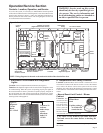
Circuit Indicator Board ............................ 4
Control Locations .................................... 5
Damper Motor ........................................ 9
Direct-Fired Burner ................................. 7
Dirty Filter Switch ................................ 10
Drive Components ................................. 3
Electronic Circuit Board with
Diagnostic Lights ................................. 5
Emergency Cut Off .................................. 6
19. Troubleshooting (cont'd)
Chart 1 (cont'd) - General Troubleshooting Guide (Check the diagnostic lights)
Index .................................................. Page
Filters ....................................................... 3
Firestat .................................................... 10
Freezestat ............................................... 10
Gas Control Systems ............................... 7
Gas Pressure ............................................ 3
Gas Pressure Switches .............................. 8
Inlet Air Controls ..................................... 9
Limit Control ........................................... 5
Main Burner ............................................. 4
Maintenance Schedule ............................. 2
Maintenance Section ......................... 2-4
Maintenance/Service Access .................... 2
Index .................................................. Page
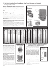
Manifold Arrangements ........................... 8
Operation/Service Section .............. 5-12
Outside Air Cutoff Control ..................... 8
Photoelectric Smoke Detector ................ 10
Photohelic Pressure Sensor ..................... 10
Pilot Assembly ........................................ 4
Potentiometer ........................................... 9
Pressure Null Switch ............................... 9
Sensing Pressure Check ........................... 6
Troubleshooting ..................................... 11
Wiring Diagram ......................... In the main
electrical box on the unit
FOR SERVICE OR REPAIR, FOLLOW THESE STEPS IN ORDER:
FIRST: Contact the Installer
Name ___________________________________________________________________________
Address ___________________________________________________________________________
___________________________________________________________________________
___________________________________________________________________________
Phone ___________________________________________________________________________
SECOND: Contact the nearest distributor (See Yellow Pages). If no listing,
contact Authorized Factory Representative, 1-800-695-1901 (Press 1).
THIRD: Contact REZNOR
®
/Thomas & Betts Corporation
150 McKinley Avenue
Mercer, PA 16137
Phone: (724) 662-4400
Model No. _____________________________________________
Unit Serial No. _____________________________________________
Date of Installation _____________________________________________
©2001 Thomas & Betts Corporation, All rights reserved. Printed in the U.S.A.
MANUFACTURER OF HEATING, COOLING, AND VENTILATING SYSTEMS
Trademark Note: Reznor
®
is registered in the United States and other countries.
(800) 695-1901; www.ReznorOnLine.com
8/01 YL Form 441OMS (Version .1)
Symptom or Problem (cont'd) Cause and Remedy (cont'd)
14. Disconnect closed; blower and burner switches in run position; control 1. Air in pilot gas line - bleed pilot line.
switch is in "winter" position;
"control power", high gas normal; "low
2. Inadequate pilot gas pressure - verify pilot gas pressure (3.5" w.c.)
gas normal"; "firestat normal"; "system switch energized"; "starter
3. Faulty pilot valve - replace pilot solenoid valve.
energized" and "freezestat normal"
lights are lit; ignitor has reached 4. Faulty ignition module - replace entire module.
1.4A and has opened the pilot valve bringing on the
"pilot valve normal"
light; but the pilot flame is not present. (After two trials the unit will go
into safety lockout requiring cycling of the main disconnect switch.)
15. Disconnect closed; blower and burner switches in run position; 1. Microamp signal on flame rod is inadequate - check position and
control switch is in "winter" position; all status lights are lit condition of flame rod and signal (minimum 0.5 microamps required.)
except
"main valve normal" light. The pilot flame is present 2. Grounding for unit or flame rod inadequate - check ground path.
and stable, but the (low stage portion or) main gas valve will not 3. Faulty main gas valve - replace main gas valve.
open, or rapid cycling of the main valve is occurring. 4. Faulty ignition module - replace ignition module.
5. Inadequate main gas pressure - verify main burner pressure.
16. Disconnect closed; blower and burner switches in run position; 1. Faulty main gas valve - replace main gas valve.
control switch is in "winter" position; all status lights are lit; the 2. Inadequate timing on high fire time delay relay - adjust setting.
pilot flame and low fire on the main burner are present and stable, 3. Faulty high fire time delay relay - replace time delay relay.
but the unit will not progress to a high fire condition. 4. High stage relay contacts are not closed - check control setting.
5. Inadequate main gas pressure - verify main burner gas pressure.
6. Faulty high stage relay - replace relay.
7. Faulty ignition module - replace entire module.