


Page 7
For troubleshooting guides and further explanation of Maxitrol Series 14 and
44 electronic modulation gas control systems, refer to the Maxitrol literature
in the owner's envelope.
The Option AG30, AG31, AG32 and AG35 electronic modulation systems
are comprised of Maxitrol Series 14 controls. Options AG30 and AG31
systems electronically maintain a constant discharge air temperature in the
range of 55-90°F (55-75°F for C.G.A.). Option AG31 includes an overriding
thermostat. Option AG32 system will maintain a constant discharge air
temperature in the range of 80-130°F. Option AG35 maintains a discharge
temperature range of 120-160°F.
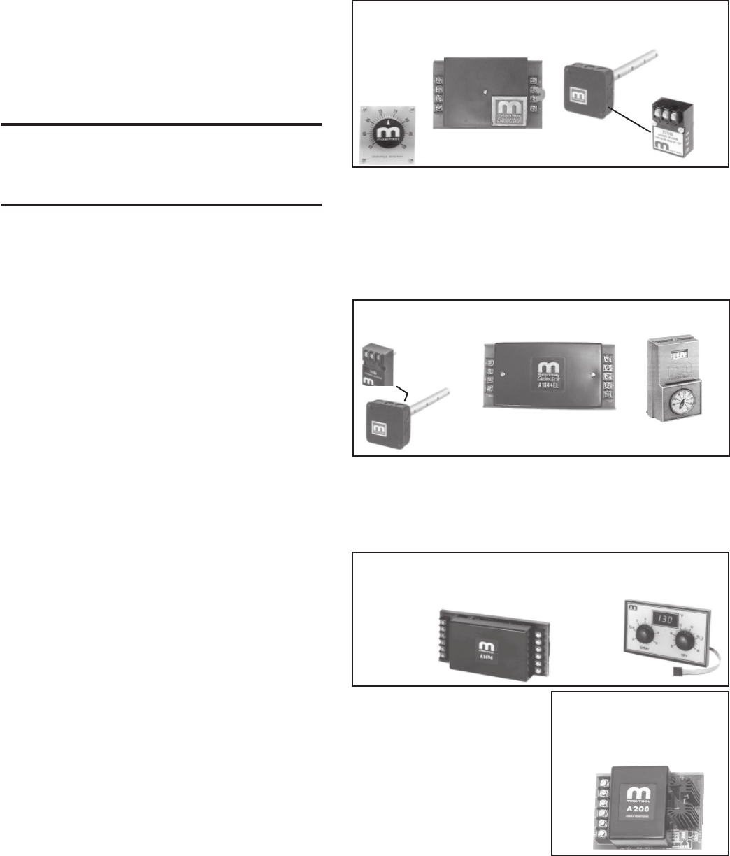
Option AG33 electronic modulation system is comprised of Maxitrol Series
44 controls. The low limit (20-60°F) and the high limit (60-140°F) for con-
trol of discharge air temperature are set at the amplifier located in the control
compartment. The space temperature is set at the remote selectrastat (55-
90°F range) located in the space. When the temperature is below the space
temperature setpoint, the control system operates the burner to automati-
cally adjust the discharge air temperature within the maximum and minimum
limits set on the amplifier.
Option AG36 is a special application gas train that is designed for controlling
the environment of a paint booth operation. The system includes a Maxitrol
A1494 amplifier, discharge air temperature sensor, dual remote discharge air
temperature selector (drying selector 80-140°F and a spray selector 60-
90°F), and two switches to control the operation of the modulating gas valve.
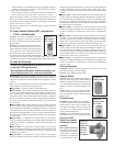
Electronic Modulation
Gas Control Option
AG37
Function: Control Option AG37
does not have a duct sensor or ampli-
fier. Instead, a Maxitrol A200 signal
conditioner is activated by a cus-
tomer-supplied input signal (either 4-
20 milliamps or 0-10 volt) to control
the modulation of the gas valve.
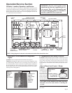
11. Gas Train Including Direct-Fired
Burner, Gas Control Systems,
Manifold Arrange-ments, and Gas
Pressure Switches
Direct-Fired Burner
Function: The design of the direct-fired burner and the con-
trolled velocity of air at the burner ensure complete combustion
through the full range of burner sizes and gas inputs as determined
by the gas control system. The velocity of air is controlled by the
profile plates and monitored by a standard low and high air pres-
sure switch.
Service: Refer to Paragraph 6 in the Maintenance Section for
instructions on burner maintenance.
WARNING: Burner profile plates are factory
set to match CFM requirements. Do not adjust
profile plates without contacting your Sales
Representative for technical assistance.
Makeup Air Gas Control Systems
• Electronic Modulation Gas Control
Options AG30, AG31, AG32, AG33, AG35,
AG36
Refer to the wiring diagrams in the main electrical box to deter-
mine which controls are on the system being serviced. NOTE: All
field-supplied control wiring for Maxitrol controls must not be
run inside conduit with line voltage wiring. To avoid any potential
electrical interference, all field-supplied wiring for Maxitrol con-
trols should be shielded wiring and must be grounded at the unit
only.
Function: These makeup air gas control systems provide heated
makeup air at a temperature controlled by a discharge air sensor.
Each system is equipped with electronic modulation controls
that modulate burner flame from 1/25th of full fire input to full
fire.
The electronic modulating-type gas controls act in response to
discharge and/or room air temperature sensors to change the gas
flow rate to the burner, thus lengthening or shortening the flame.
The BTU output is varied (modulated) to maintain the required
discharge air temperature.
These modulating gas control options are electronic because in all
cases the gas valve acts to adjust the flow of the gas to the main
burner in response to DC volts emanating from an amplifier.
When the DC voltage is between 0 and 5 volts, the main valve seat
is closed. Low fire flow is accomplished through a mechanical
bypass. The low fire flow rate is set at the factory and should not
need adjustment. However, if adjustment is necessary, refer to
the Maxitrol literature that is included in the heater owner's enve-
lope.
All of the electronic modulating gas control burner systems in-
clude low fire start. On an initial call for heat, the main burner
ignites at its lowest input. During mild weather, the burner may
then cycle off. Such full shutdown can be dictated by the outdoor
ambient cutoff control. As the outside air temperature climbs
above the setpoint of the outdoor ambient control, the burner
control circuit is de-energized. When moderately cold outside air
temperatures exist, the burner will modulate between low flame
and high flame. Low fire start and the outdoor ambient control
prevent the makeup air system from heating already warm air and
providing "too much" heat to the building.
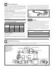
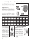
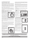
Amplifier,
P/N 133229
Selector,
P/N
133230
Figure 17 - Components of the Gas Control System used in
Option AG36 designed specifically for paint booths - controls
are mounted on a remote console
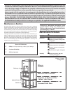
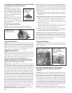
Figure 15 - Components of the Gas Control System (Maxitrol
Series 14) used in Gas Control Options AG30, AG31, AG32,
and AG35
Temperature
Sensor
Temperature
Selector
Amplifier,
P/N 148590
Mixing
Tube
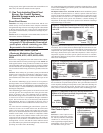
Figure 16 - Components of the Gas Control System (Maxitrol
Series 44) used in Gas Control Option AG33
Amplifier,
P/N 157915
Temperature
Sensor,
P/N 119617
Temperature
Selector, P/N 86990
Mixing Tube,
P/N 90323
tioning properly. If the ignition controller locks out and there is no
other cause, the controller module must be replaced.
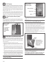
Figure 18 - Maxitrol A200
Signal Conditioner,
P/N 134170, used in Gas
Control Option AG37