


Page 4
4. Air Pressure
Profile plate sensing tubes should be checked quarterly and cleaned no
less than semiannually. If the sensing tubes become even partially
blocked, false pressure readings may be relayed. To clean, remove the
screened end caps. Clean the screens and the tubes, if necessary. Re-
place the cleaned end caps. Check the pressure differential across the
profile plate using a slope gauge. Air pressure differential should be
between -.5" and -.7" w.c.
To attach the slope gauge, open the control compartment door panel.
Just below the junction box, locate the tubing connections. Remove the
cap at each connection and attach the slope gauge using two field-
supplied 1/4" x 1/8" female NPT barbed tubing connections. For in-
structions on measuring air pressure, see Service Section, Paragraph 9.
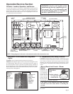
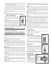
5. Circuit Indicator Board (check
lights)
The circuit indicator board is located in the control compartment elec-
trical box (See Figure 7). Check operation of all indicator lights by
switching lights that are not lit with one that is currently lit. Replace all
burned out indicator bulbs (P/N 125189).
Figure 4 - Circuit
Indicator Board,
P/N 151263
Check bulbs not
lit with other
bulbs; replace
any burned out
bulbs
Row of Bulbs
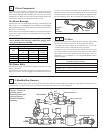
6. Main Burner and Pilot Assembly
For the most part, the burner and pilot are self cleaning. However, if the
application is extremely dirty or dusty, cleaning of the burner and pilot
may be necessary. Inspect the burner annually. Follow these instruc-
tions. If it is necessary to replace any parts, use only factory-autho-
rized replacements.
1) Turn off the gas and power supply to the system.
2) Remove the door panels in the burner/control cabinet (four or six
depending on whether or not the system has return air). Locate the
pilot.
3) Disconnect the two ignition wires (male and female quick connec-
tions) and disconnect the flame sensor lead at the burner. Remove
the set screw located in the ignitor tube (set screw holds the brass
bushing in place). Carefully remove the brass bushing and the igni-
tor.
Check the hot surface ignitor for cracks or unusual deterioration.
Check the flame rod for integrity. Replace the flame rod (P/N 131188)
and/or the hot surface ignitor (P/N 121865) if not in good condition.
4) Clean the burner and pilot by back-flushing, using high pressure air
(40-80 lbs). Continue until dust particles are completely expelled
from both the upstream and downstream sides of the burner.
CAUTION: Wear eye protection while pressure
cleaning and drilling.
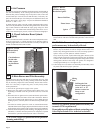
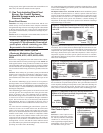
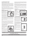
Figure 5 - Burner
End Plate showing
Hot Surface Ignitor
Ignitor
Flame Sensor
Burner End Plate
If air pressure does not unplug burner orifices or pilot tube, drill
burner orifices with a Size #50 drill and/or pilot tube with a Size #55
drill.
WARNING: Do not enlarge burner ports or
performance may be drastically affected.
Inspect the upstream and downstream sides of the mixing plates.
Remove any accumulation of scale or foreign material with a wire
brush. If any mixing plate fasteners are loose or missing, tighten or
replace. Always use zinc plated or stainless fasteners.
If any cracks are present, replace that mixing plate. Because of the
effect of flame temperature on the metal, fasteners may be difficult
to remove. Be careful not to damage the gaskets that go between the
mixing plates and the burner body. The gaskets are designed to
overlap approximately 1/16" for tight air seal.
5) Follow Steps in reverse order to re-install the pilot assembly. Close
all panels and check for proper operation.
WARNING: Burner profile plates are factory set
to match CFM requirements.
Do not adjust profile plates without contacting your
Sales Representative for technical assistance.
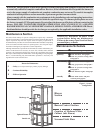
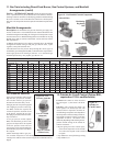
Figure 6 - Illustration of the first Burner Section
Mixing
Plate
Burner
Full length of the
burner is made up of a
series of 6" or 12"
burner sections in a
linear or oval
configuration
S
R
S