


Page 6
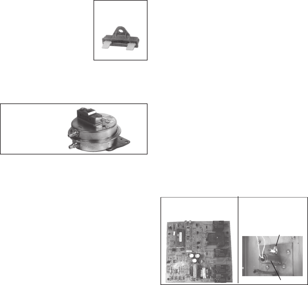
10. Ignition System
Location: Ignition Controller Module in the Control Compartment
Electrical Box (See Figures 7 and 13.); Ignitor and Flame Sensor on the
Burner (See Figure 14.)
Hot Surface Ignition System with Prepurge
Time Delay and Flame Sensor with 100%
Lockout
Function: The ignition system including the controller, the hot surface
ignitor, and the flame sensor function to ignite and prove the pilot
flame. When there is a call for heat, the modular ignition controller is
energized. When the controller reads 1.4 amps going to the hot surface
ignitor, it opens the pilot valve for a 15-second trial for ignition. After
the pilot flame rod senses pilot flame, the main gas valve is energized. If
the pilot flame rod does not sense a pilot flame, the controller shuts
down the pilot valve for a 10-second interpurge and then opens it again
for a second ignition trial. If pilot flame is not proven on the second
trial, the ignition controller locks out and must be manually reset by an
interruption of the main circuit (disconnect switch).
Service: The modular ignition controller does an internal self-check
each time that it is energized and will lockout if not found to be func-
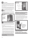
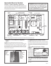
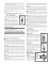
Figure 13 - Ignition Control
Module in the Electrical
Compartment, P/N 157953
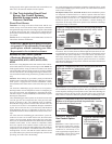
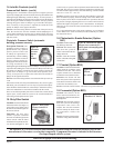
Figure 14 - Ignitor, P/N
121865, and Flame
Sensor, P/N 134706, on
the Burner
• Emergency Cut Off Limit Control
Function: The emergency cut off is a fus-
ible link high temperature limit which pro-
vides one-time redundant protection
against overheating. If the temperature
sensitive limit control malfunctions, the
electrically activated emergency cutoff will
shutdown the system.
Service: If this limit activates, the manual
limit control has failed and must be re-
placed. The cause for activating the emer-
gency cut off limit control must be found and corrected before re-
starting the system.
9. Air Pressure Switches
Location: Control Compartment Electrical Box (See Figure 7.)
Depending on the options selected, there are two or four switches.
• Low Air Flow Switch
Function: The low air flow switch is a velocity pressure switch that
monitors air flow across the burner. Until the air flow attains adequate
volume for combustion, the switch remains open. When the switch
recognizes adequate air volume, it closes, permitting both the pilot and
burner to operate. Low pressure switch is normally open; it closes on
pressure rise at .2" w.c. Do not alter or adjust setting.
• High Air Flow Switch
Function: The high air flow switch is a velocity pressure switch that
monitors air flow across the burner. If the high air flow switch senses air
velocity above the prescribed limit, it will shutdown gas flow to the
burner. High pressure switch is normally closed; it opens when pres-
sure rises above .9" w.c. Do not alter or adjust setting.
• Bypass Damper Air Flow Switches (systems
with Air Control Options AR19, AR20, AR22, AR23,
AR32, AR33, AR34, AR36, or AR37)
Function: With a bypass damper, the volume of outside air supplied
to the building is adjusted by a manually set potentiometer (Option
AR19 and AR22) or automatically by a pressure null switch (Option
AR20 or AR23), a photohelic pressure switch (Option AR36 or AR37),
or a field-supplied computer signal (Option AR33 or AR34). With
Options AR19, AR20, AR33, and AR36 the supply air is varied by
adjusting the position of a damper at the blower discharge. With Op-
tions AR22, AR23, AR34, and AR37, a return air damper is adjusted to
vary the volume of return air. The unit is arranged so that a fixed amount
(20%) of the rated volume flows over the burner at a constant velocity.
The remainder (80%) of the rated air volume flows either through a
balancing bypass damper or a combination of bypass and return air
dampers. As the supply air volume is varied by the return air or dis-
charge damper, the balancing damper is adjusted to maintain the re-
quired air velocity over the burner. Adjustment of the bypass damper is
controlled by the bypass damper pressure switches. One pressure
switch is normally closed with a setting of .5" w.c.; the other is nor-
mally open with a setting of .65" w.c. balancing bypass damper.
Sensing Pressure Check: (requires a slope gauge, several feet of
1/4" O.D. tubing and two 1/4" O.D. barbed tees.)
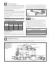
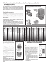
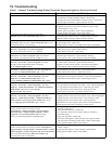
Figure 11 - ECO
Limit Control,
P/N 82414
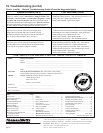
Figure 12 - Air
Pressure Switch
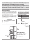
8. Temperature Limit Safety Controls (cont'd)
Attach a slope gauge (0 to 1.0" scale) to the tubing connections in the
control compartment. The two connections are located below the elec-
trical control box. Remove the caps on the 1/8" NPT test connections
and attach the slope gauge. (The recommended method for attaching the
slope gauge is to use field-supplied 1/8" female NPT x 1/4" O.D. barbed
hose connections.)
A) If the system includes an optional discharge damper, before measur-
ing burner differential air pressure, check to be sure that the damper
is fully open.
B) With the blower operating, the pressure differential on the slope
gauge should read between -.5" and -.7" w.c. If the slope gauge
reading is within those limits, no adjustments are necessary.
If the slope gauge reading is not within the setpoint limits of the air
flow switches (.2" to .9" w.c.), and the system is operating, replace
the air pressure switch(es).
If the slope gauge reading is not between -.5" and -.7" w.c., but
within the setpoint limits, clean the sensing tubes (Follow the in-
structions in Maintenance Section, Paragraph 4).
C) When air pressure is within the proper range, turn the disconnect
switch OFF. Disconnect the manometer and the slope gauge. Re-
place the caps removed to connect the slope gauge.
Service: If the pressure check determines that an air flow switch is not
functioning properly, the switch cannot be serviced and must be re-
placed with an identical replacement. Low air pressure switch is P/N
86986; high air pressure switch is P/N 86987; bypass damper switches,
P/N 87249 (normally closed, set to open at .5" w.c.) or P/N 87250
(normally open, set to close at .65" w.c.).
Setting 305
o
F
Ignitor
Sensor