


Page 3
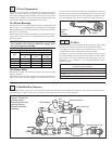
Inlet Pressure Tap
Valve
Valve
Regulator
Manifold Pressure Tap
Gas
Supply
Pilot
Regulator
Pilot Solenoid Valve
Pilot Pressure Tap
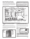
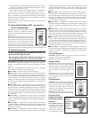
3. Manifold Gas Pressure
Semiannually, check the gas pressure to the burner and to the pilot. Measure both manifold pressure and pilot supply pressure with the blower in
operation. Refer to Figure 3 for pressure tap locations. Verify against pressures listed on the rating plate.
Figure 3 - Location of
pressure taps for
measuring burner and
pilot gas pressure.
Measure with blower
operating.
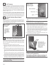
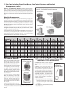
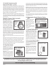
1B. Blower Belts
Check belts for proper tension and wear. Adjust belt tension as needed.
Replace worn belts.
Proper belt tension is important to the long life of the belt and motor. A
loose belt will cause wear and slippage. Too much tension will cause
Figure 2 -
Belt
Tension
2. Filters
If the system includes filters, check the filters quarterly. Filters could
be either in the optional inlet base or in an optional filter cabinet.
If the filters are in the perimeter of the inlet base; they are two-inch
permanent filters. Remove and clean the filters as needed.
If the filters are in a filter cabinet (the filter cabinet is always between
the inlet base and the burner/control section), remove the filter cabinet
door panels to access the V-bank filter rack. Filters may be either 2"
disposable, 1" or 2" permanent, or 1" or 2" disposable pleated. Clean or
replace as needed.
Sizes and Quantity of Filters in the Filter Cabinet
( same for all types of filters)
Size 109 112 115 118 122 125
16" x 16" 4 4 - - 16 16
16" x 20" 4466- -
16" x 25" - - 6688
1. Drive Components
The blower, motor and drive components are located in the blower
cabinet at the top of the system. Systems with horizontal discharge
have a cabinet with eight removable door panels. Systems with vertical
discharge have a cabinet with six removable door panels. Remove the
panels required to access the components being serviced.
1A. Blower Bearings
All blowers are Class I with pillow block bearings. Clean the fitting and
add type NLG-2 or -2 standard grade grease. Add grease with a handgun
until a slight bead of grease forms at the seal. Be careful not to unseat
the seal by over lubricating.
NOTE: If unusual environmental conditions exist (temperatures below
32
o
F or above 200
o
F; moisture; or contaminants) more frequent lubri-
cation is required.
CAUTION: If the blower is unused for more than
three months, the bearings should be purged with
new grease prior to startup.
3/4 (19mm)
S
R
R E
excessive motor and blower bearing wear. If adjustment is required,
adjust belt tension by means of the adjusting screw on the motor base
until the belt can be depressed 1/2" to 3/4" (Figure 2). Tighten the lock
nut on the adjusting screw. Be sure the belt is aligned in the pulleys.
Pilot Manifold
Recommended Bearing Lubrication Schedule in Months
Bearing Bore Diameter (Inches)
RPM
1/2 >1 to >1-1/2 to
to 1 1-1/2 1-15/16
to 500 6 6 6
501 - 1000 6 6 6
1001 - 1500 5 5 5
1501 - 2000 5 4 5