


32 UV-SVP01A-EN
Note: The Tracer Zn.520 unit
controller only supports
cascade control by controlling
the discharge air temperature.
Therefore, the controller
requires both a space
temperature input and a
discharge air temperature
input.
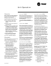
Trane configures the Tracer
®
ZN.520 Unit Controller at the fac-
tory per the selected unit configu-
ration. The controller is applied
classroom unit ventilator configu-
rations that support modulating
valves, 2-position valves, econo-
mizer damper (modulating only),
direct expansion (DX) cooling, 1-
and 2 -stage electric heat, face-
and-bypass damper, baseboard
heat, dehumidification, and ge-
neric I/O. The controller also sup-
ports HIGH and LOW fan speeds
with exhaust fan output on 1- and
2-speed fan applications.
1. Isolation valves are 2-position only.
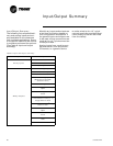
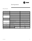
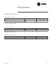
Configurable parameters
Rover service tool uses the unit
type to determine and download
many other aspects of the unit con-
figuration, such as the default ana-
log input configuration, the default
binary input configuration, and the
default binary output configura-
tion.
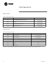
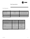
Cooling source
q None
q Hydronic (main coil
changeover)
q Dedicated hydronic
q DX
Heating source
q None
q Hydronic
q Dedicated hydronic
q Steam
q Electric heat
q Hydronic (main coil
changeover) + dedicated
hydronic (auxiliary coil)
q Hydronic (main coil
changeover)
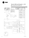
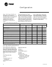
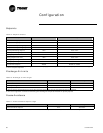
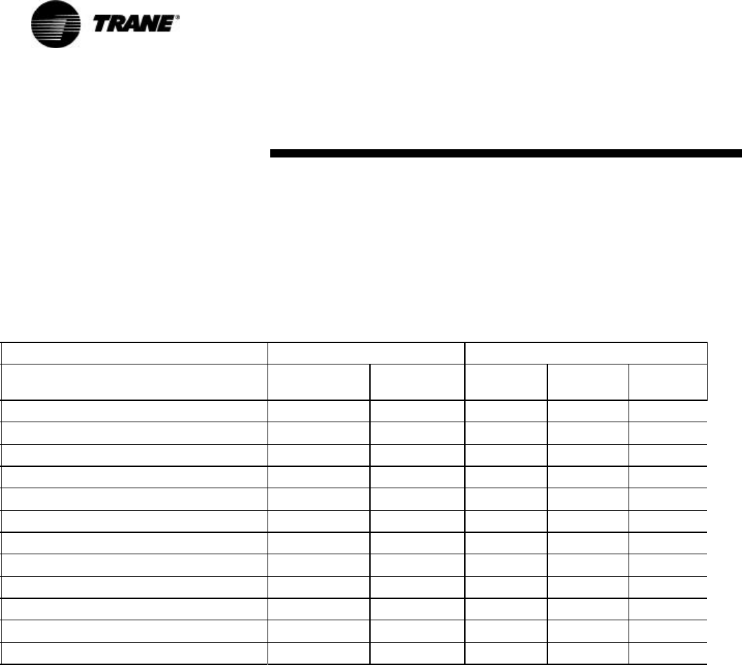
Table 9: Typical applications supported
Configuration Type of valve Options
Modulating 2 position
Electric Heat
(1 or 2 stage)
Economizer
Damper
Baseboard
Heat
2-pipe cooling only
ü ü ü ü
2-pipe heating only ü ü ü ü
2-pipe changeover
ü ü ü ü ü
4-pipe
ü ü ü ü
4-pipe changeover ü ü ü ü
2-pipe face bypass heating only ü
1
ü ü
2-pipe face bypass changeover ü
1
ü ü
4-pipe face bypass ü
1
ü ü
DX cooling only
NA NA
ü
DX cooling, 2-pipe heating
ü ü ü ü
DX cooling, electric heating
NA NA
ü ü ü
Electric heat only (1 or 2 stage)
NA NA
ü ü ü
Configuration