


48 UV-SVP01A-EN
Important! When viewing the
Tracer ZN.520 through the
Rover service tool, it is
important that the version be
up-to-date. To help ensure that
your version is the most
recent, contact you local Trane
sales representative or service
center.
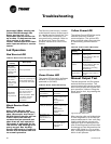
Led Operation
Red Service LED
Black Service Push
Button
Note: If the Service push
button is held down for more
than 15 seconds, the Tracer™
ZN.520 Unit Controller will un-
install itself from the ICS
communication network and
shut down all unit operation.
This mode is indicated by the
red Service LED flashing once
every second. See the Red
Service LED section. Use Rover
service tool to restore the unit
to normal operation.
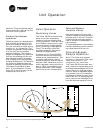
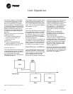
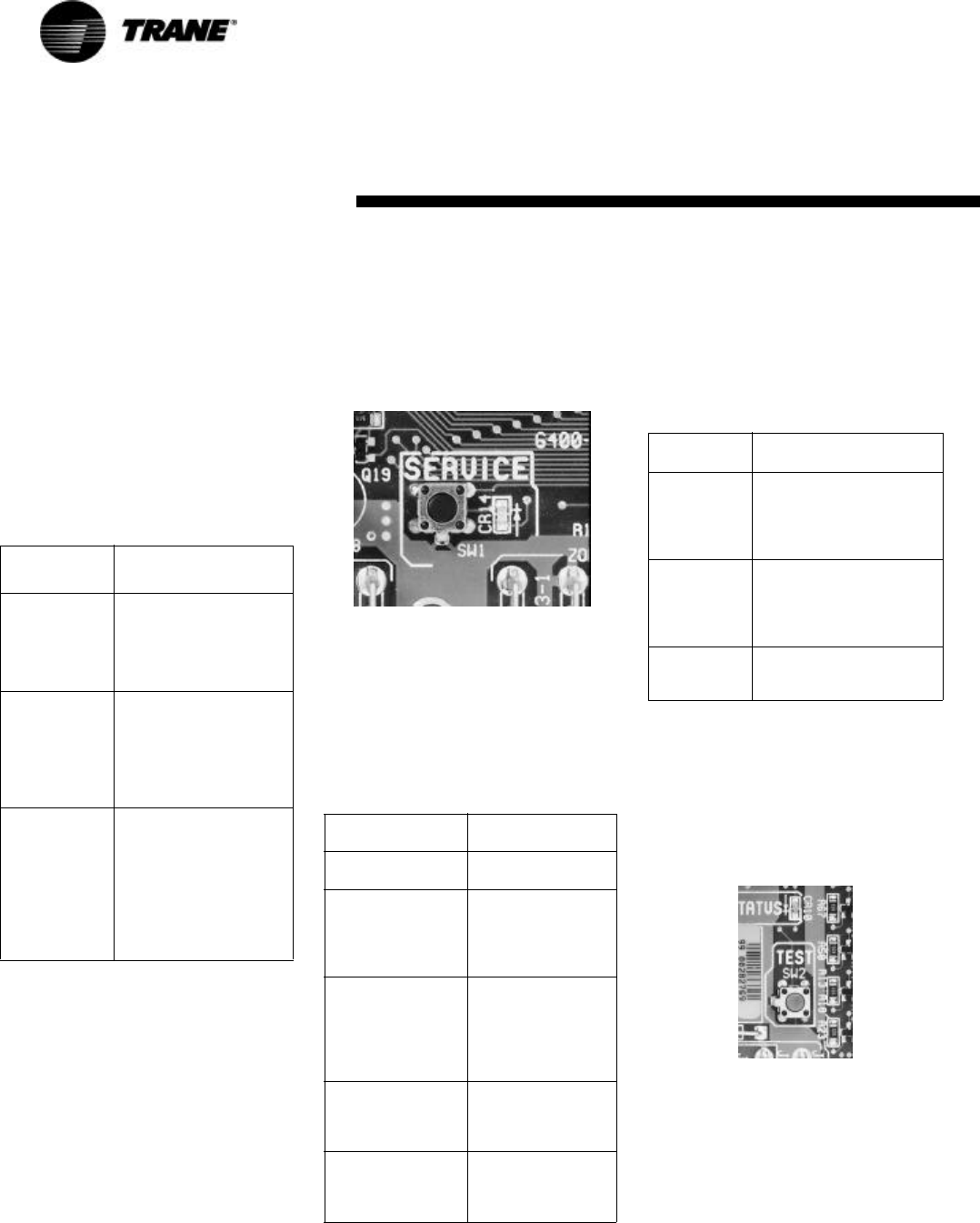
The Service push button, located
at the bottom center of the control-
ler, can be used to install the Trac-
er™ ZN.520 Unit Controller in a
communication network. Refer to
the Rover and Tracer Summit
product literature for more infor-
mation.
Figure 25: Black service button
Green Status LED
The green LED normally indicates
whether or not the controller is
powered on (24 VAC).
Yellow Comm LED
The yellow Comm LED blinks at the
rate the controller receives
communication. The yellow LED
does not blink when the controller
is transmitting communication
data.
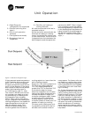
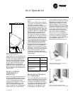
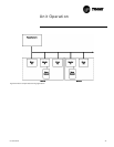
Manual Output Test
The test sequence verifies output
and end device operation. The
manual output test can be conduct-
ed to verify output wiring and actu-
ator operation, without using the
Rover service tool, by pressing the
test button.
Figure 26: Blue test button
Many service calls are initiated due
to unit diagnostics, so the test se-
quence attempts to clear unit diag-
nostics and restore normal unit
operation prior to testing the out-
puts. If the diagnostics remain after
an attempt to clear diagnostics, the
status LED lights in a
two-blink pat-
tern, indicating the diagnostic con-
dition is still present.
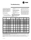
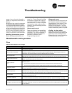
Table 23: Red service LED activity
Red LED
activity
Description
LED is OFF
continuously
after power is
applied to the
controller.
Normal operation.
LED is ON
continuously,
even when
power is first
applied to the
controller.
Someone is pressing the
Service push button or
the controller has failed.
LED flashes
about once
every second.
Un-install (normal
controller mode). Use
Rover service tool to
restore the unit to
normal operation. Refer
to the Rover product
literature for more
information.
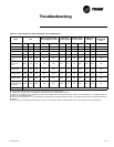
Table 24: Green status LED activity
Green LED
activity
Description
LED is ON
continuously.
Power ON (normal
operation).
LED blinks (1 blink
per second).
The controller is in
manual output test
mode.
No diagnostics
present.
LED blinks (2
blinks per second).
The controller is in
manual output test
mode.
One or more
diagnostics are
present.
LED blinks (1/4
second on, 1/4
second off for 10
seconds).
Wink mode.
LED OFF. Power is off.
Controller failure.
Test button is
pressed.
Table 25: Yellow comm LED activity
Yellow LED
activity
Description
LED OFF
continuously.
The controller is not
detecting any
communication. (Normal
for standalone
applications.)
LED blinks or
flickers.
The controller detects
communication. (Normal
for communicating
applications, including
data sharing.)
LED ON
continuously.
Abnormal condition or
extremely high traffic on
the link.
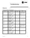
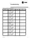
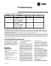
Troubleshooting