


UV-SVP01A-EN 54
Troubleshooting
Note
1
: The generic binary output (TB4-1, TB4-2) state is unaffected by all unit diagnostics.
Note
2
: During manual output test, these diagnostics make the green status LED light in a two-blink pattern. For more information see,
Manual Output Test, on page 48 for more information.)
Note
3
: When the entering water temperature is required but not present, the Tracer™ ZN.520 Unit Controller generates a diagnostic to
indicate the sensor loss condition. The controller automatically clears the diagnostic once a valid entering water temperature value is
present (non-latching diagnostic). When the entering water temperature sensor fails, the controller prohibits all hydronic cooling operation,
but allows the delivery of heat when heating is required. In the
COOL mode, all hydronic cooling is locked-out, but normal fan and outdoor
air damper operation is permitted.
Note
4
: These diagnostics are non-latching and automatically reset when the input is present and valid.
Note
5
: When the outdoor air temperature sensor has failed or is not present, the Tracer™ ZN.520 Unit Controller generates a diagnostic to
indicate the sensor loss condition. The controller automatically clears the diagnostic once a valid outdoor air temperature value is present
(non-latching diagnostic). When the outdoor air temperature sensor fails or is not present, the controller prohibits economizer operation. A
value of Enable or Disable for nviEconEnable overrides these decisions, regardless of the presence of an outdoor air temperature value or
failure.For more information see, Interoperability, on page 12 for more information.)For more information see, Data Sharing—LonWorks,
on page 46 for more information.)
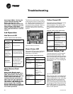
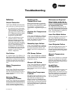
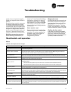
Translating Multiple Diagnostics
The controller senses and records
each diagnostic independently of
other diagnostics. It is possible to
have multiple diagnostics present
simultaneously. The diagnostics
are reported in the order they oc-
cur.
Resetting
Diagnostics
There are many ways to reset unit
diagnostics:
q Automatically by the controller
q By initiating a manual output
test at the controller
q By cycling power to the
controller
q By using a building automation
system
q By using the Rover service tool
q By cycling the fan switch from
off to any speed setting
Automatically
The Tracer™ ZN.520 Unit Control-
ler includes an automatic diagnos-
tic reset function. This function
attempts to automatically recover
a unit when the Low Coil Temper-
ature Detection diagnostic occurs.
When this diagnostic occurs, the
controller responds as defined in
Table 28: Tracer™ ZN.520 Unit Controller
diagnostics
.
After the controller detects the
Low Coil Temperature Detection
diagnostic, the unit waits 30 min-
utes before invoking the automatic
diagnostic reset function. The au-
tomatic diagnostic reset function
clears the Low Coil Temperature
Detection diagnostic and attempts
to restore the controller to normal
operation. The controller resumes
normal operation until another di-
agnostic occurs.
If a Low Coil Temperature Detec-
tion diagnostic recurs within 24
hours after an automatic diagnos-
tic reset, you must manually reset
the diagnostic. See other possible
methods for resetting diagnostics
in this section.
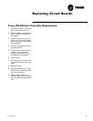
Manual output test
The
TEST button on the controller
may be used either during installa-
tion to verify proper end device
operation or during troubleshoot-
ing. When depressed, the Test but-
ton, the controller exercises all
outputs in a predefined sequence.
The first and last steps of the se-
quence reset the controller diag-
nostics.
(See “Manual Output Test” on
page48.for more information.)
Cycling power
When turned-off, the controller's
24 VAC power, and re-applies
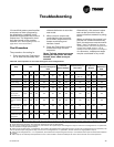
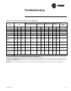
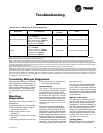
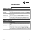
Invalid Unit Configuration
2
Fan—
DISABLED
Valves—DISABLED
Outdoor air damper—DISABLED
Face bypass damper—DISABLED
DX/electric heat—DISABLED
Baseboard heat—DISABLED
Non-latching Communicated or manual reset
Normal
Fans—E
NABLED
Valves—ENABLED
Outdoor air damper—ENABLED
Face bypass damper—ENABLED
DX/electric heat—ENABLED
Baseboard heat—ENABLED
Non-latching Communicated or manual reset
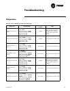
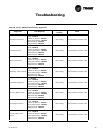
Table 28: Tracer™ ZN.520 Unit Controller diagnostics
Diagnostic Unit Response
Latching/non-
latching
Reset