


12 UV-SVP01A-EN
Communication Configurations
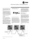
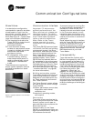
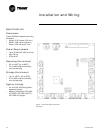
Stand-Alone
In a stand-alone configuration,
commands for operation are deter-
mined based on input from the
zone sensor, humidity sensor, and
factory- or field-mounted time-
clock.(See Figure 6: “Typical class-
room unit ventilator installation”)
q The timeclock is wired to the
Tracer ZN.520 to index the unit
between occupied and
unoccupied modes.
q A unit-mounted, analog,
outside-air temperature sensor
is used to initiate the dry bulb
economizer and freeze
avoidance routines.
q On changeover units, a unit-
mounted, analog, entering
water temperature sensor is
used to automatically control
the system in the heat/cool
mode.
These sensors are required for
proper system operation and are
provided as standard on stand-
alone units.
Figure 6: Typical classroom unit ventilator
installation
Communication Interface
Important! To help ensure
optimal performance of the
Rover service tool, please use
the latest version. To obtain
the latest version contact your
local Trane sales represent-
tative or service technician.
Note: Refer to the Tracer
system manuals for more
information on communica-
tions.
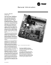
The Tracer ZN.520 communicates
via Comm5 (LonTalk) to a building
management system, the Rover
service tool, and other unit control-
lers on the communications link.
Each Tracer ZN.520 requires a
unique address for the system to
operate properly. Every Tracer
ZN.520 has this address (Neuron
ID) embedded in the microproces-
sor, which eliminates the need for
field-addressing of the units. Each
unit also ships from the factory
with a unit identification tag. (See
“Location Identifier” on page38,
for more information.)
Building automation system
Trane offers a state-of the art front-
end building automation system
designed to coordinate and moni-
tor Trane equipment and control-
lers: Tracer Summit.
The Tracer Summit system allows
the user to monitor and/or change
Tracer ZN.520:
q status, parameters, sensor data,
diagnostics, and internal
variables; and
q setpoints, operating modes,
and outputs.
Service tool
Trane also offers a service tool to
work in conjunction with the Tracer
Summit system or with peer-to-
peer and stand-alone systems: the
Rover service tool.
Communication to the Tracer
ZN.520, or multiple controllers, can
also be accomplished by using the
ICS software service tool.
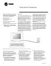
A personal computer running Rov-
er may be directly connected to a
standalone Tracer ZN.520; con-
nected to the communications jack
in the Trane zone sensor; or con-
nected to a communicating unit’s
Tracer ZN.520 unit controller, to ac-
cess all of the units on a communi-
cating link.
Rover allows the user to interface
with the Tracer ZN.520, but will not
allow any advanced control (e.g.
equipment scheduling or trend-
ing). To purchase a copy of the ICS
software service tool, contact the
BAS department at your local
Trane dealer.
Interoperability
Trane has lead the industry with
BACnet interoperability and Trane
is now expanding the realm of in-
teroperable solutions by offering
LonMark certified unit controllers.
The Tracer ZN.520 controller con-
forms to the LonMark Space Com-
fort Controller profile. (See
“Appendix—Data Lists” on
page64, for more information.)
This allows the ZN.520 to be used
as a unit controller on other control
systems that support LonTalk and
the SCC profile. Now building own-
ers have more choices and design
engineers have more flexibility to
meet the challenges of building au-
tomation.