


UV-SVP01A-EN 41
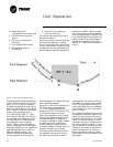
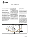
The entering water must be five
degrees or more above the space
temperature to allow hydronic
heating, and five degrees or more
below the space temperature to al-
low hydronic cooling.
If the desired water temperature is
available, the unit begins normal
heating and cooling operation. If
the measured entering water tem-
perature is not adequate for the
desired heating or cooling, the
controller begins the entering wa-
ter temperature sampling logic.
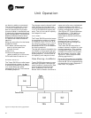
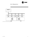
The Tracer™ ZN.520 Unit Control-
ler operates the modulating valves
and dampers based on a heating
or cooling capacity calculated by
the control algorithm. The control
algorithm calculates the heating or
cooling capacity based on the
measured space temperature, the
active setpoint and the discharge
air temperature. When the mea-
sured space temperature is within
the active heating and cooling set-
points, the heating and cooling ca-
pacity approaches zero.
Cooling Operation
During the COOLING mode, the
Tracer ZN.520 controller attempts
to maintain the space temperature
at the active cooling setpoint.
Based on the controller’s occupan-
cy mode, the active cooling set-
point is one of the following:
q Occupied cooling setpoint
q Occupied standby cooling
setpoint
q Unoccupied cooling setpoint
The controller uses the measured
space temperature, the active
cooling setpoint, and discharge air
temperature along with the con-
trol algorithm to determine the re-
quested cooling capacity of the
unit (0-100%). The outputs are con-
trolled based on the unit configu-
ration and the requested cooling
capacity.
Heating Operation
During the HEATING mode, the
Tracer ZN.520 controller attempts
to maintain the space temperature
at the active heating setpoint.
Based on the controller’s occupan-
cy mode, the active heating set-
point is one of the following:
q Occupied heating setpoint
q Occupied standby heating
setpoint
q Unoccupied heating setpoint
The controller uses the measured
space temperature, the active
heating setpoint, and discharge air
temperature along with the con-
trol algorithm to determine the re-
quested heating capacity of the
unit (0-100%). The outputs are con-
trolled based on the unit configu-
ration and the requested heating
capacity.
Fan Operation
For multiple fan speed applica-
tions, the Tracer ZN.520 controller
allows separate default fan speeds
to be configured for heating and
cooling modes. When the fan
mode switch is in the AUTO posi-
tion or no hardwired input exists,
the fan operates at the configured
default fan speed (i.e, HIGH).
The Tracer ZN.520 controller also
allows the default fan speed to be
configured as AUTO. When the fan
speed switch is in the AUTO posi-
tion and the default fan speed is
configured as AUTO, the unit may
change fan speeds based on the
requested heating or cooling ca-
pacity. In this mode, the unit fan
will operate at LOW speed until the
requested capacity requires HIGH
fan speed operation to maintain
space comfort.
The fan mode request can be ei-
ther hardwired or communicated
to the Tracer ZN.520 controller.
When both are present, the com-
municated request has priority
over the hardwired input. Addi-
tional flexibility in the controller al-
lows the fan speed switch to be
disabled. When this occurs, the
unit will operate at the default fan
speed unless a communicated re-
quest is present.
During OCCUPIED, OCCUPIED
STANDBY, and OCCUPIED BYPASS
modes, the fan will normally oper-
ate continuously at the appropri-
ate fan speed. The fan will only be
OFF in these modes when the MAN-
UAL OUTPUT TEST has been initiat-
ed, a latching diagnostic is
present, or the communicated or
hardwired fan speed is OFF. (See
“Manual Output Test” on
page48.for more information.)
During the UNOCCUPIED mode, the
unit fan is controlled OFF. When ca-
pacity is required to maintain the
unoccupied heating or cooling set-
point, the unit fan is controlled to
high speed regardless of a hard-
wired or communicated fan speed.
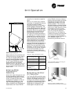
Fan Off Delay
When a heating output is con-
trolled off, the Tracer™ ZN.520
Unit Controller automatically
holds the fan on for an additional
30 seconds. This 30-second delay
gives the fan time to blow off any
residual heat from the heating
source, such as a steam coil. When
the unit is heating, the fan off de-
lay is normally applied to control
the fan; otherwise, the fan off de-
lay does not apply.
Fan Start On High Speed
On a transition from off to any oth-
er fan speed, the Tracer™ ZN.520
Unit Controller automatically
starts the fan on high speed and
runs the fan at high speed for 0.5
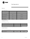
Table 21: Absolute two-speed fan
switch points
Fan Speed
Change
Absolute
Temperature Error
Low to High 2.00 °F
High to Low 1.25 °F
Unit Operation