


UV-SVP01A-EN 55
Troubleshooting
power, the unit cycles through a
power-up sequence and clears all
timers.
By default, the controller attempts
to reset all diagnostics at power-
up. Diagnostics present at power-
up and those that occur after pow-
er-up are handled according to the
defined unit diagnostics sequenc-
es (For more information see,
Table
28: Tracer™ ZN.520 Unit Controller diag-
nostics, on page 52 for more information.).
Building automation system
Some building automation sys-
tems (i.e., Tracer Summit building
automation system) can reset di-
agnostics in the Tracer™ ZN.520
unit controller. For more complete
information, refer to the product
literature for the building automa-
tion system.
Rover service tool
Rover service tool can reset diag-
nostics in the Tracer™ ZN.520 unit
controller. For more complete in-
formation, refer to the Rover In-
stallation, Operation, and
Programming manual.
Diagnostic reset
Any device that can communicate
the network variable nviRequest
(enumeration “clear_alarm”) can
reset diagnostics in the Tracer™
ZN.520 unit controller. The con-
troller also attempts to reset diag-
nostics whenever power is cycled.
Cycling the fan switch
If the user cycles the fan speed
switch from
OFF to any speed, the
controller resets all diagnostics.
Diagnostics may recur immediate-
ly if the problem still exists.
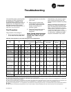
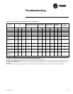
Questionable unit operation
Fans
Table 29: Fan outputs do not energize
Probable cause Possible Explanation
Unit wiring
The wiring between the controller outputs and the fan relays and contacts must be present and correct
for normal fan operation.
No power to the controller
If the controller does not have power, the unit fan does not operate. For the Tracer™ ZN.520 Unit
Controller to operate normally, it must have an input voltage of 24 VAC. When the green LED is off
continuously, the controller does not have sufficient power or has failed.
Unit configuration
The controller must be properly configured based on the actual installed end devices and application.
When the unit configuration does not match the actual end devices, the fans may not work correctly.
Random-start observed
After power-up, the controller always observes a random-start from 5 to 30 seconds. The controller
remains off until the random-start time expires.
Power-up control
wait
When power-up control wait is enabled (non-zero time), the controller remains off until one of two
conditions occurs:
1. The controller exits power-up control wait once it receives communicated information.
2. The controller exits power-up control wait once the power-up control wait time expires.
Diagnostic present
A specific list of diagnostics affects fan operation. For more information see, Tracer™ ZN.520 Unit
Controller diagnostics, on page 52 for more information.)
Manual output test
The controller includes a manual output test sequence you can use to verify output operation and
associated output wiring. However, based on the current step in the test sequence, the unit fan may not
be on. For more information see, Manual Output Test, on page 48 for more information.)
Fan mode OFF
When a local fan mode switch (provided on the Trane zone sensor) determines the fan operation, the
off position controls the unit
OFF.
Requested mode OFF
You can communicate a desired operating mode (such as
OFF, HEAT, and COOL) to the controller. When
OFF is communicated to the controller, the unit controls the fan OFF. There is no heating or cooling.
UNOCCUPIED operation When the controller is in the UNOCCUPIED mode, the fan is cycled.
Cycling fan operation/continuous
The controller operates the fan continuously when in the
OCCUPIED, OCCUPIED STANDBY, or OCCUPIED
BYPASS mode. When the controller is in the unoccupied mode, the fan is cycled between HIGH speed and
OFF with capacity.