


............ www.truemfg.com ............
True Food Service Equipment, Inc.
15 15
INSTALLATION / OPERATION INSTRUCTIONS
4. If all operating conditions are
normal, the voltage supply at the
compressor terminals balanced and
within limits, the compressor crankcase
temperature within normal limits,
and the amperage drawn within the
specified range, the motor protector
may be defective, and should be
replaced.
If the operating conditions are normal
and the compressor is running
excessively hot for no observable
reason, or if the amperage drawn is
above the normal range and sufficient
to repeatedly trip the protector, the
compressor has internal damage and
should be replaced.
IF THE COMPRESSOR RUNS
BUT WILL NOT REFRIGERATE
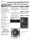
1. Check the refrigerant charge.
Check the evaporator surface
to determine if it is evenly cold
throughout, or if partially starved. A
lack of charge may be indicated by
light, fluffy frost at the evaporator inlet.
Add refrigerant if necessary.
2. Check the compressor suction
pressure. An abnormally low pressure
may indicate a loss of refrigerant
charge, a malfunctioning capillary tube,
a lack of evaporator capacity possibly
due to icing or low air flow, or a
restriction in the system.
Often a restriction in a drier or strainer
can be identified by frost or a decrease
in temperature across the restriction due
to the pressure drop in the line. This
will be true only if liquid refrigerant
is in the line at the restricted point,
since any temperature change due to
restriction would be caused by the
flashing of liquid into vapor as the
pressure changes.
Any abnormal restriction in the system
must be corrected.
3. Check the compressor discharge
pressure. An abnormally high
discharge pressure can cause a loss of
capacity, and can be caused by a dirty
condenser, a malfunctioning condenser
fan, or air in the system.
4. If the suction pressure is high,
and the evaporator and condenser
are functioning normally, check the
compressor amperage draw. An
amperage draw near or above the
nameplate rating indicates normal
compressor or unit may have damaged
valves.
An amperage draw considerably below
the nameplate rating may indicate a
broken suction reed or broken
connecting rod in the compressor.
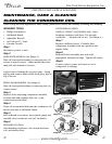
DIAGNOSIS AND
REPLACEMENT OF FREEZER
CABINET COMPONENTS
1. Defrost Time Clock
A. Check timer motor to be sure
it runs.
B. Check contacts on the defrost
timer.
C. Check solenoid windings for
continuity to ensure contact
switching.
D. Check to be sure defrost
actuator pins are in proper
position.
E. Check all wires in the timer for
tightness to terminals and
broken wires.
2. Defrost Control On The
Evaporator Drain Pan
A. If the defrost time is always
35 minutes (or whatever duration
the elapsed time adjustment is set
at) and the fan motors do not delay
after a defrost cycle and it has been
determined that the solenoid in the
defrost clock is functioning, change
the defrost control in the evaporator
compartment in the top of the
freezer. This control is attached to the
evaporator drain pan.
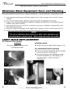
3. Coil Defrost Heater
A. Lower the evaporator cover.
Disconnect the coil heater by removing
the wire nuts at the point where the
heater joins the electrical circuit of the
freezer in the evaporator compartment.
Check heater for continuity with an
ohmmeter. If the heater is defective,
cut the bale wires holding the heater
to the coil and remove the heater.
Replace with a new heater using bale
wires provided.
4. Drain Tube Heater
A. Lower the evaporator cover.
Disconnect the drain tube heater by
removing the wire nuts at the point
where the heater joins the electrical
circuit of the freezer in the evaporator
compartment. Check the drain tube
heater with an ohmmeter.
B. If the drain tube heater is
defective, disconnect the drain tube
from the rigid plastic drain, bend the
tabs that hold the evaporator drain pan
to the evaporator cover and raise the
drain pan so that the flexible heater is
visible, pull heater out of the plastic
drain tube and replace. Connect heater
to the electrical circuit in the evaporator
compartment.
5. Cabinet Temperature
Control
A. Remove the two screws on the
right side of the evaporator housing
that holds the control mounting plate.
Reach behind the evaporator housing
on the control side of the cabinet
and pull the control bulb out of the
receptacle in the roof of the cabinet.
Disconnect the wires from the control.
Check control for continuity, replace if
defective.