


............ www.truemfg.com ............
True Food Service Equipment, Inc.
6 6
INSTALLATION / OPERATION INSTRUCTIONS
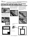
INSTALLATION OF OPTIONAL LEGS AND
CASTORS
Removing Kickplate:
Before installing optional legs or castors the kickplate
at the bottom of the unit will need to be removed. To
remove kickplate first remove any loose items from
inside the unit (shelving, baskets, etc). Then remove the
top plastic lid which you gain access to the inside of the
unit. Lay the unit on it's side. Make sure the unit is on
soft packing material so not to scratch the cabinet. Then
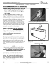
backout 1/4" hex head screws all around the base of the
unit. (See illustration 1 and image 1). After the kickplate
has been removed reinstall all of the hex head screws
back into the base of the unit. (See image 2). castors
and legs are to be installed in the corners of the base of
the unit.
Unit Leveling With Castors:
Four leveling shims have been provided for leveling on
uneven floors when using optional castors. Shims must be
positioned between the base of the unit and bearing race.
True recommends a four shim limit to any single castor.
A. Turn the bearing race counter-clockwise until the
cabinet is level. Level front to back and side to side.
(diagonally)
B. Install the desired number of shims, making sure the
slot of the shim is in contact with the threaded stem of
the castor.
C. If more than one shim is used, turn the slot at a 90°
angle so they are not in line.
D. Turn the bearing race clockwise to tighten and
secure the castor by tightening the anchoring bolt
with a 3/4 inch open-end wrench, socket, or the tool
provided.
CAUTION
To avoid damage to lower rail assembly, slowly raise unit
to upright position after installing castors.
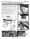
Unit Leveling With Legs:
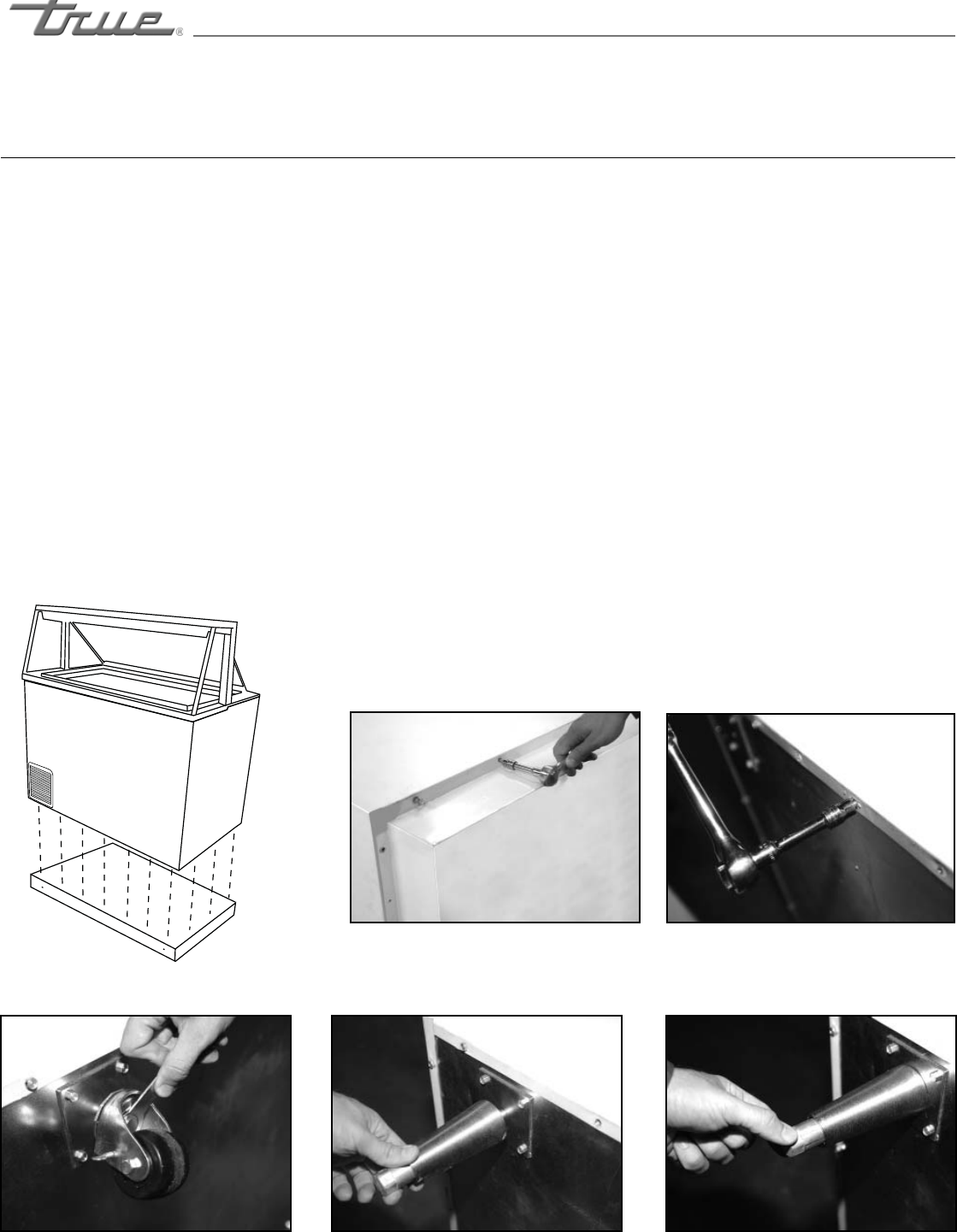
Turn the legs clockwise to tighten in each corner of the
cabinet base. (See image 4). After legs are secure level the
unit by backing out the end the leg shown in image 5. Turn
the end of the leg until the cabinet is level. Level front to
back and side to side (diagonally).
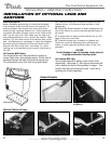
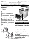
Optional Castors and Legs
Standard Kickplate
Illustration 1.
Image 1 (Removing kickplate).
Image 2 (Reinstalling screws from
kickplate).
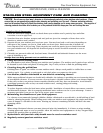
Image 3 (Installing castors).
Image 4 (Installing legs).
Image 5 (Leveling legs).