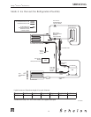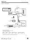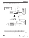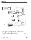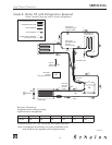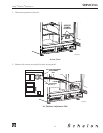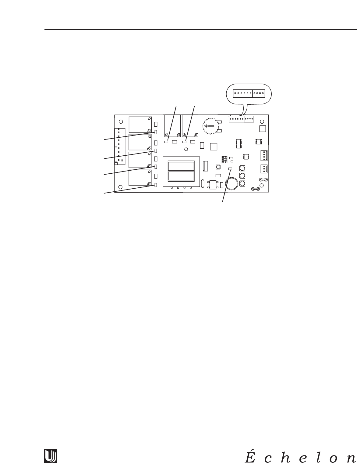
Check Lights on Control Board
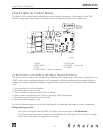
The lights on the control board indicate power to the labeled component. The exception is the “REF
VALVE” (refrigeration valve). When this light is off, the refrigeration bypass valve is powered.
1. PWR 5. HOT GAS
2. REF VALVE 6. H2O IN – water inlet
3. FAN 7. COMP
4. H2O PUMP – (water circulating)
CLRCO2075 CONTROL BOARD DIAGNOSTICS
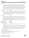
This section can be used to aid in pinpointing a problem when diagnosing a unit. Every component in the
CLRCO unit can be energized separately and its operation verified by following the procedure below. In
addition to verifying individual component operation the function of the circuit board can be checked as
well.
1. Turn power switch to the off position.
2. Disconnect power from the unit.
3. Turn ice thickness adjustment dial to the +5 setting.
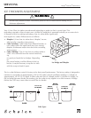
4. Add a jumper to thermistor pins 9 and 10. See page 39 for pin locations.
5. Disconnect one pink lead from circuit board.
6. Reconnect power supply to unit.
Any of the following steps can be checked individually or combined with others to check components.
Refrigeration bypass valve
This valve is energized when the REF VLV light on the circuit board is not illuminated.
First check to see if the valve is energized. It should feel hot to the touch. If it is not check voltage
at the valve itself and at the output from the board.
CLRCO035
-1
-2
-3
-4
-5
5
4
3
2
1
0
6
5
4
3
2
7
1
10 9 8 7 6 5 4 3 2 1
Thermistors:
Ice/Ref 1 and 2
Cond to 3 and 4
Ref to 5 and 6
27
Design
■
Features
■
Performance
SERVICING


