


28
Design
■
Features
■
Performance
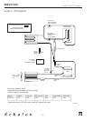
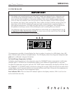
Compressor COMP
To energize the compressor touch the previously disconnected pink lead back to the board. You
should hear the compressor start up and the green COMP light will illuminate. If it does not start
check voltage at the compressor and at the output from the board. If the green light does not illu-
minate first remove both pink wires from the board and directly jump the two spade connectors
together. If the light does not illuminate still then the board is defective. If the light does illuminate
there is an open pump overflow circuit. This circuit should only be open when the P60 pump is
overfilled with water. This would signal a defective pump or blocked drain line. When doing this
do not start and stop the compressor frequently or the compressor overload protect will trip.
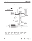
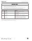
Hot gas valve Hot Gas
Make sure the pink lead is disconnected from the board before beginning this procedure. Turn the
power switch to the on/ice position. You should hear the hot gas valve click and the green HOT
GAS light should illuminate. If the valve does not operate but the green light comes on check volt-
age at the valve and board output. If the green light does not illuminate first check the On/Off/Cln
switch for continuity. If the switch is operating properly and set to the on position the green HOT
GAS light should be illuminated.
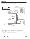
Water valve H20 IN
Make sure the pink lead is disconnected from the board before beginning this procedure and the
power switch is still in the off position. Turn the switch to the CLN position. The water valve
should energize and the H20 IN green light should illuminate. You should see water filling into the
trough. If water is not filling but the green light is on check voltage at the valve and board output.
Also, verify that the water supply is hooked up and turned on. If the light does not illuminate
check the Cln switch for continuity. If the switch is operating properly and set to the CLN position
the green H20 IN light should be illuminated.
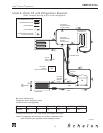
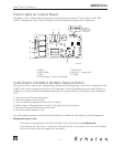
Refrigeration valve REF VLV
Condenser fan COND FAN
Water circulation pump H20 PUMP
Before beginning this ensure the pink lead is disconnected from the board and the switch is in the
off position.
Turn ice thickness adjustment dial to +2 setting. This should energize the REF VLV relay and illumi-
nate the green REF VLV light. You should hear the valve click and it should feel warm to the touch.
Continue turning the dial to the “0” setting. At this point the condenser fan should activate and the
green COND FAN light will illuminate. Finally, turn the dial to -2 and the water circulation pump
will energize. If there is water in the trough the pump should begin to pump water over the ice-
mold. If the water is low the pump may not pump water but make splashing noise only.
At the conlusion of this testing:
1. Disconnect power supply to unit.
2. Connect both pink leads to the circuit board.
3. Remove jumper to thermistor pins 9 and 10. See page 39 for pin locations.
4. Turn ice thickness adjustment dial to the “0” setting.
5. Connect power to the unit.
6. Turn power switch to the ice position.
SERVICING