


02/2005 13 www.U-LineService.com
™
CO2075FF — Ice Maker/Refrigerator
CAUTION
Plumbing installation must observe all state and local
codes. All water connections MUST BE made by a licensed/
qualified plumbing contractor. Failure to follow
recommendations and instructions may result in damage
and/or harm.
WARNING
To prevent accidental electrocution, make certain
that the floor surfaces surrounding the unit are
dry whenever power is removed from, or applied
to, the unit.
Water Supply Connection
When connecting the water supply, follow these
guidelines:
• Review the local plumbing codes before you install the
unit.
• Connect to the cold water supply.
• The water pressure should be between 20 and 120 psi.
• Install a shut-off valve in the 1/4 inch OD water supply
line.
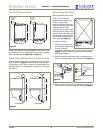
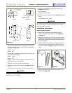
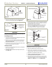
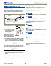
• Connect sufficient tubing to the unit so that tubing
may be looped, allowing the unit to be removed for
cleaning and servicing (see Figure 32). However, make
certain that the tubing is not pinched or damaged
during installation.
• U-Line recommends the use of copper tubing for
installation.
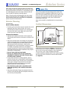
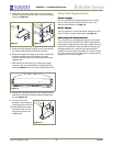
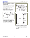
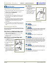
To connect to water supply:
1. Install the 1/4 inch OD copper water line from the
main water source (see Figure 30).
2. Locate the compression fitting and ferrule packed with
the unit. Slide the compression fitting and ferrule over
the 1/4-inch OD water supply line. Do not use thread
sealing compound or tape. Using two wrenches,
tighten the compression fitting on the supply line (see
Figure 31).
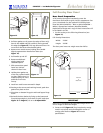
3. Carefully bend the water supply line into position and
connect the line to the solenoid valve (see
Figure 32
).
Avoid kinking the water supply line.
IMPORTANT
Normal operation creates some vibration. A water supply
line contacting cabinet wall may cause excessive noise
during operation or damage to the line.
4. For recessed installations, allow extra water supply line
length to provide slack for easy removal from the
recessed area (see
Figure 32
). This will also safeguard
against kinking the line.
5. Go on to
7 Prepare Power Supply
.
6Prepare Plumbing
Water
Connection
Figure 31Figure 30
Figure 32