


www.U-LineService.com 14 02/2005
™
CO2075FF — Ice Maker/Refrigerator
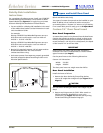
Electrical Specifications
CAUTION
Electrical installation must observe all state and local
codes. This unit requires connection to a grounded (three-
prong), polarized receptacle that has been placed by a
qualified electrician.
The unit requires a grounded and polarized 115 VAC,
60 Hz, 15A power supply (normal household current).
An individual, properly grounded branch circuit or circuit
breaker is recommended. GFCI (ground fault circuit
interrupter) is usually not required for fixed location
appliances and is not recommended for your unit because
a GFCI could be prone to nuisance tripping. However, be
sure to consult your local codes.
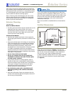
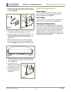
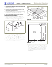
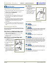
See Figure 33 for recommended receptacle location.
WARNING
SHOCK HAZARD — Electrical Grounding Required.
• Never remove the round grounding prong from
the plug and never use a two-prong grounding
adapter.
• Never use an extension cord to connect power to
the unit.
Go on to 8 Level the Unit.
Leveling Information
IMPORTANT
It is extremely important that the unit is level. If it is not
level, the ice mold will not fill evenly.
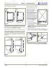
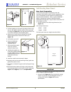
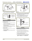
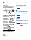
1. Use a level to check the
levelness of the ice maker
from front to back and
from side to side. Level
should be placed along
top edge and side edge
as shown (see Figure 34).
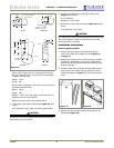
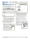
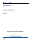
2. If the ice maker is not level, adjust the feet on the
corners of the unit as necessary (see
Figure 35
).
3. Check the levelness after each adjustment and repeat
the previous steps until the unit is level. Go on to
9 Install the Unit
.
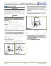
Installation Tip
If the room floor is higher than the floor in the cut-out
opening, adjust the rear feet to achieve a total unit rear
height of 1/8
"
less than the opening’s rear height. Shorten
the unit height in the front by adjusting the front feet.
This allows the unit to be gently tipped into the opening.
Readjust the front feet to level the unit after it is correctly
positioned in the opening.
7 Prepare Power Supply
1-1/2"
7"
23-11/16"
Figure 33
8 Level the Unit
Check
Level
Figure 34
Turn Foot to Adjust
Figure 35