F35425 (February 2006) Page 18 of 40
C24GA SERIES CONVECTION STEAMERS - SERVICE PROCEDURES AND ADJUSTMENTS
A. If 24VAC is present, then replace ignition
control module and retest. It may take up to
3 seconds for the module to reset if main
power is turned off then back on.
B. If 24VAC is not present, then ensure that
transformer is receiving 120VAC input. If
ignition control module transformer is
receiving proper voltage, then replace
ignition control module transformer and
retest.
IGNITION TEST
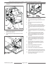
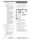
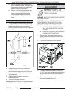
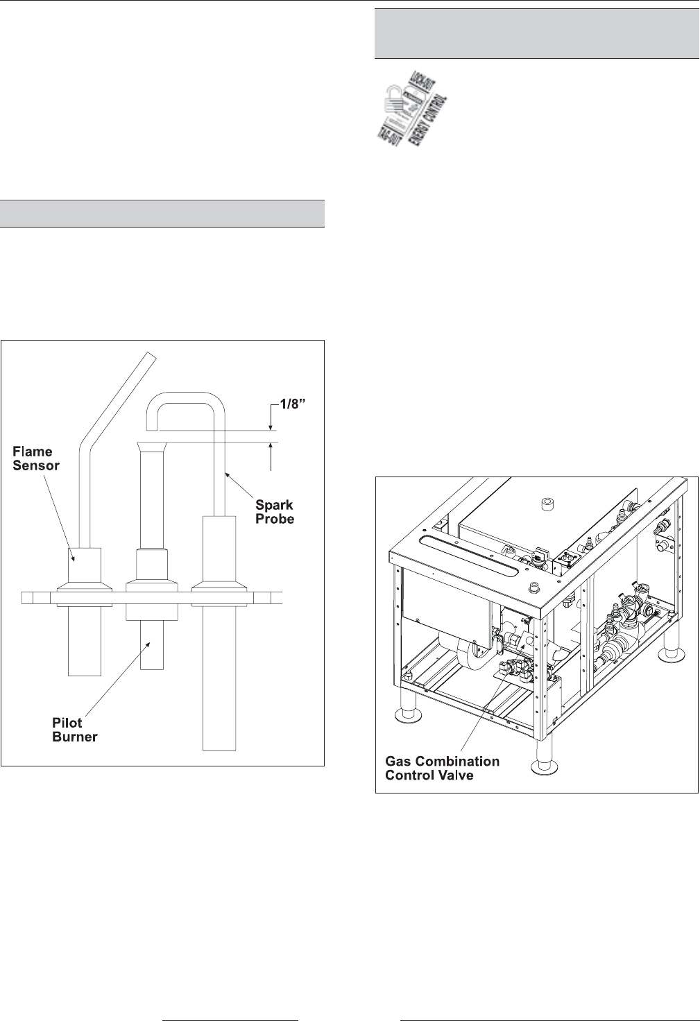
1. The gap between the spark probe and the pilot
burner should be approximately 1/8". If the gap
appears to be excessive or poor sparking is
occurring, remove the electronic ignition pilot and
adjust gap.
2. Inspect the ceramic flame rod insulator for
cracks or evidence of exposure to extreme heat,
which can permit leakage to ground. If either of
these conditions exist, then replace the pilot
igniter assembly.
3. Check the ignition cable for tightness or
damaged insulation.
4. Check unit for proper operation.
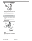
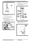
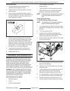
Inspect the pilot burner orifice. This should be approxi-
mately 1/8" in diameter and free of debris.
MANIFOLD PRESSURE
ADJUSTMENT
WARNING: DISCONNECT THE
ELECTRICAL POWER TO THE
MACHINE AND FOLLOW LOCKOUT /
TAGOUT PROCEDURES.
WARNING: SHUT OFF THE GAS SUPPLY BEFORE
SERVICING THE UNIT.
WARNING: ALL GAS JOINTS DISTURBED DURING
SERVICING MUST BE CHECKED FOR LEAKS.
CHECK WITH A SOAP AND WATER SOLUTION
(BUBBLES). DO NOT USE AN OPEN FLAME.
A. CHECK ALL JOINTS PRIOR TO THE GAS
VALVE (SOLENOID) BEFORE LIGHTING
THE UNIT.
B. CHECK ALL JOINTS BEYOND GAS VALVE
(SOLENOID) AFTER UNIT IS LIT.
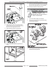
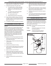
1. Remove front, right and left side panels from
cabinet base as outlined under COVERS AND
PANELS.
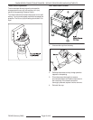
2. Turn the gas combination control valve off.
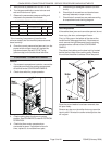
3. To measure the manifold pressure, remove the
1/8" NPT plug (pressure tap) on the outlet side of
the gas combination control valve and attach a
manometer.
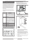
4. Turn the gas supply valve and the main power
switch on. Allow generator to fill.


