


F35425 (February 2006) Page 34 of 40
C24GA SERIES CONVECTION STEAMERS - TROUBLESHOOTING
TROUBLESHOOTING
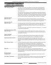
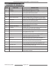
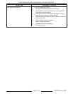
SEQUENCE OF OPERATION
STEP FUNCTION DESCRIPTION
1 Power On Power Switch is switched to the on position.
2 Fill Stage 1 Boiler fills with fast fill water valve, (3.7 GPM).
3 Low Level Probe Confirmation Low Level Probe, (LLCO), is confirmed then power is applied to
burner system, fast fill valve is turned off.
4 Burner Operation Power is supplied to operating pressure switch.
5 Blower Blower is turned on by operating pressure switch.
6 Blower Pressure Switch Blower air pressure switch is closed when fan is up to speed,
(0.35" to 0.4" WC) and supplies 24 VAC to the ignition module.
7 Pilot Ignition Module turns on spark ignition and supplies power to combination
valve pilot valve, (PV & PV/MV terminals).
8 Flame Sense Flame sense probe confirms pilot flame.
9 Main Burner Ignition module supplies power to gas combination control valve,
(MV & PV/MV terminals), burner ignites.
10 Generator Initial Heat Up Generator heats up.
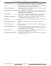
11 Fill Stage 2 Generator 190°F thermostat supplies signal to water level control
to continue filling with trickle valve, (0.25 GPM).
12 Generator Full Boiler will fill till high water probe is confirmed.
13 Ready Operating pressure switch activates ready light and supplies timer
motor power at 3.5 to 4.0 PSI.
14 Full Pressure Generator burner system is terminated at 3.5 to 4.0 PSI.
15 Low Pressure Generator burner system will turn on at 2.5 to 3.5 PSI and operate
till generator pressure reaches 3.5 to 4.0 PSI.
16 Water Level Water level is electronically controlled between the upper and
middle probe operating the trickle fill valve, 0.25 GPM.
17 Cooking Timer is set and door switch is closed power will be supplied to
steam valve, cavity drain valve relay, and cook light.
18 Cold Water Condensate Thermostat located in drain assembly will supply power to cold
water condensate valve to maintain drain temp below 140°F.
19 End Cook Cycle Timer supplies power to buzzer, removes power from steam valves,
cook light, & cavity drain valve relay.
20 Power Off Power Switch is switched to the off position.
21 Power Down Power is removed from burner and water level controls.
22 Drain Power is supplied to drain timer, drain valve is powered for
approximately 16 minutes.