


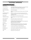

HALF-SIZE CONVECTION OVENS - ELECTRICAL OPERATION
20
SEQUENCE OF OPERATION
Ignition Module
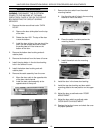
1. 24VAC supplied to ignition module as described
under oven sequence of operation
A. 15 second prepurge period
1) No-ignition light is on
2) Cavity blower motor removes any
residual gas from combustion chamber
B. 10 second spark period
1) Gas valve energized
2) No-ignition light is off
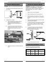
2. The flame is monitored by a DC voltage of at least 5
microamps passing from the ignitor probe through
the flame to ground.
A. If the flame is detected before 10 seconds:
1) Sparking is terminated
2) Gas valve held open
3) Monitoring of flame continues
B. If a flame is not established after the 10
second spark period
1) a second 15 second prepurge period
2) A second 10 second spark period
C. If a flame is not established after the second
10 second spark period
1) a third 15 second prepurge period
2) A third 10 second spark period
D. If a flame is not established after the third 10
second spark period, the module will go into
lock out
1) No ignition light on
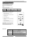
3. To reset the ignition module perform one of the
following
A. Turn power switch off; then on
B. Open and close the door
C. Turn the temperature control all the way off
then back to the set temperature
4. If a flame is established then is extinguished before
the temperature control is satisfied, the no ignition
light will be on and the ignition module will attempt
to light the burner in the sequence described above.
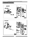
Gas Oven
NOTE:
A combination of terminal numbers and wire
numbers will be used to describe the circuit paths. The
complete path will be described when a component is
energized.
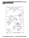
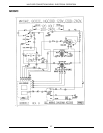
Solid State Control (Gas)
NOTE:
Use GCO2D Schematic
1. Conditions
A. Supply voltage to unit
1) L1 to power switch: wire #1; J1-1; wire #1
2) L2 to power switch: wire #2; J1-2; wire #2
3) Good chassis ground for:
a. Ignition module: GND
b. No ignition light: wire #48; GND;
wire #6; J1-6; wire #6; GND
c. Gas valve: wire #48; GND;
d. Ignition transformer: GND
B. Power switch off
C. Oven at room temperature
D. Temperature control off
E. Manual gas valve open
F. Door switch closed
G. Cooldown switch off
H. Timer off
2. Power switch turned "on" (voltage at terminals of
power switch)
A. Power On lamp lights: wire #34/J1; wire
#41/37
B. Control powered: wire #34; wire #33/3; J1-3;
wire #3; door switch; wire #27/4; J1-4; wire
#4/36/35; terminal 8; terminal 9 (120 VAC) or
terminal 10 (200-240 VAC); wire #39/37
C. Blower motor energized: wire #34; wire #33/3;
J1-3; wire #3; door switch; wire #27/4; J1-4;
wire #4/11; J1-11; wire #11; wire #13/7; J1-7;
wire #7/37
1) Blower motor reaches operating speed,
blower motor centrifugal switch closes
3. Control set to cook temperature, contacts 6/7 close
A. Ignition transformer primary powered: terminal
6; wire #9; J1-9; wire #9; BK/BL wire; WH/BK
wire; wire #7; J1-7; wire #7/37
B. Heating lamp lights: terminal 6; wire #43; wire
#42/37
4. 24 VAC from ignition transformer secondary to
ignition module: transformer secondary wire #52;
centrifugal switch; wire #54; terminal 24V of control
module; GND
5. Ignition module operates (see ignition module
sequence of operation)