


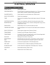

HALF-SIZE CONVECTION OVENS - ELECTRICAL OPERATION
25
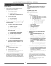
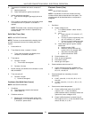
Cook
1. Conditions
A. Oven has reached set temperature in heat
mode
2. Time is set and start key pressed.
3. Oven cycles at set temperature.
NOTE:
In pulse mode (initiated at the beginning of
the bake cycle), the blower motor is operated in 45
second cycles, with the first cycle being off then 45
seconds on. The pulse time cannot be longer than
the bake time.
4. Time expires.
A. Buzzer sounds continually.
5. Oven continues to cycle at set temperature.
NOTE:
The blower motor and heaters are de-
energized when the door is opened and the oven is
in the cook mode.
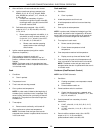
Cook and Hold
1. Conditions
A. Oven has reached set temperature in heat
mode
2. A bake temperature and time is set.
3. A hold temperature and time is set and start key
pressed.
4. Oven cycles at set temperature.
NOTE:
In pulse mode (initiated at the beginning of
the bake cycle), the blower motor is operated in 45
second cycles, with the first cycle being off then 45
seconds on. The pulse time cannot be longer than
the bake time.
5. Time expires in cook mode.
A. Buzzer sounds (short beep).
B. Control lowers temperature to hold
temperature.
6. Oven temperature reaches hold temperature.
A. Display counts up time and flashes "hold"
7. Oven continues to cycle at hold temperature until
oven is turned off or the hold function is turned off.
NOTE:
The blower motor and heating elements are
de-energized when the door is opened and the oven
is in the hold mode.
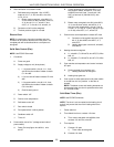
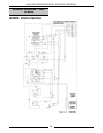
Cooldown (Elec/Electronic Control)
NOTE:
Use ECO2C Schematic
1. Conditions
A. Cooking completed, oven temperature needs
to be lowered.
B. Power/cooldown switch on
2. Power/cooldown switch to cooldown
A. Control transformer primary powered: wire
#26/4; J1-4; wire #4/94; wire #97/7; J1-7; wire
#7/2A; fuse; J1-2; wire #2; L3
3. Control powered
A. 6 VAC from secondary of control transformer -
wire #16; J1-16; J2-3; J2-2; J1-15; wire #15
B. 12 VAC from secondary of control transformer
- wire #14; J1-14; J2-1; J2-2; J1-15; wire #15
4. Control verifies cooldown mode: 16 to 18 VDC
output on J2-11; J1-20; wire #20/21;
power/cooldown switch; wire #29; J2-5
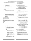
5. After verification of cooldown mode:
A. Solid state relay energized: 16 to 18 VDC
output on J2-11; J1-20; wire #20; wire #19;
J1-19; J2-10
1) Blower motor energized: wire #26/4; J1-
4; wire #4/34; ss relay contacts;; wire #
(11 high or 12 low ); J1-(11 high or 12
low); wire #(11 high or 12 low); wire
#13/7; J1-7; wire #7/37
B. Contactor coil will not be energized.
C. The door position signal is not read.