


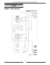
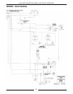
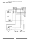
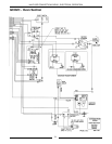

HALF-SIZE CONVECTION OVENS - ELECTRICAL OPERATION
24
4. Buzzer sounds: wire #34/64; timer contacts 1/4; wire
#66; wire #65/37
5. Timer turned to off.
A. Contacts 1/4 open
1) buzzer de-energized
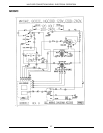
Cooldown (Elec/Solid State Control)
NOTE:
Use ECO2D Schematic
1. Conditions
A. Cooking completed, oven temperature needs
to be lowered.
B. Power switch on
2. Cooldown switch on
A. Blower motor energized: power switch; wire
#34/33/36/ motor speed switch; wire #11 high
or 12 low ); J1-(11 high or 12 low); wire #(11
high or 12 low); wire #13/7; J1-7; wire #7/37;
power switch
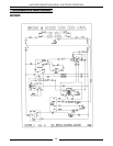
Electronic Control (Elec)
NOTE:
Use ECO2C Schematic
NOTE:
A combination of terminal numbers and wire
numbers will be used to describe the circuit paths. The
complete path will be described when a component is
energized.
Heat
1. Conditions
A. Fuses are good.
B. Supply voltage to unit (three phase)
1) L1 to power/cooldown switch: wire #1;
J1-1; fuse; wire #1A/1 and one side of
heater contacts C1: wire #61
2) L2 to one side of heater contacts C2: wire
#62
3) L3 to:
a. Motor: wire #2; J1-2; fuse; wire
#2A/7; J1-7; wire #7/13
b. Contactor coil: wire #2; J1-2; fuse;
wire #2A/7; J1-7; wire #7/50
c. Primary of control transformer: wire
#2; J1-2; fuse; wire #2A/7; J1-7;
wire #7/97
d. one side of heater contacts C3: wire
#64
4) Good chassis ground electronic control:
terminal 8 of control; J2-8; J1-6; wire #6;
GND
C. Power/cooldown switch "off"
D. Oven at room temperature
E. Door switch closed
F. Fan speed switch in either position
2. Power/cooldown switch turned "on"
A. Control transformer primary powered: wire
#26/4; J1-4; wire #4/94; wire #97/7; J1-7; wire
#7/2A; fuse; J1-2; wire #2; L3
3. Control powered from secondary of control
transformer:
A. 6 VAC - wire #16; J1-16; J2-3; J2-2; J1-15;
wire #15
B. 12 VAC - wire #14; J1-14; J2-1; J2-2; J1-15;
wire #15
4. Control set to desired temperature
A. Control verifies heat mode: 16 to 18 VDC
output on J2-11; J1-20; wire #20/21; J1-21;
power/cooldown switch; contacts of switch are
open and no return voltage to J2-5
B. Control verifies that door is closed: 16 to 18
VDC output on J2-11; J1-20; wire #20/27; door
switch; wire #3; J1-3; J2-4
5. After verification of heat mode and door closed,
A. Solid state relay energized: 16 to 18 VDC
output on J2-11; J1-20; wire #20; wire #19;
J1-19; J2-10
1) Blower motor energized: wire #26/4; J1-
4; wire #4/34; ss relay contacts;; wire #
(11 high or 12 low ); J1-(11 high or 12
low); wire #(11 high or 12 low); wire
#13/7; J1-7; wire #7/37
B. Contactor coil energized: wire #43; J2-13; J2-
15; J1-5; wire #5; wire #50/7; J1-7; wire
#7/2A; fuse; J1-2; Wire #2; L3
1) Heating elements energized
a. L1; wire #61; C1; Wire #70; wire
#75; C3; Wire #64; L3
b. L1; wire #61; C1; Wire #74; wire
#71; C2; Wire #62; L2
6. Oven reaches set temperature
A. Power removed from contactor coil
1) Heating elements de-energized
7. Oven cycles on electronic control until
power/cooldown switch is moved from the "on"
position or the door is opened.
NOTE:
The blower motor and heating elements are
de-energized when the door is opened and the oven
is in the heat mode.