


HALF-SIZE CONVECTION OVENS - ELECTRICAL OPERATION
23
5. After verification of cooldown mode:
A. Solid state relay energized: 16 to 18 VDC
output on J2-11; J1-20; wire #20; wire #19;
J1-19; J2-10
1) Blower motor energized: wire #26/4; J1-
4; wire #4/34; ss relay contacts;; wire # 9;
J1-9; wire #11; J1-11; wire #11; wire
#13/7; J1-7; wire #2; J1-2; wire #2; L2
B. Contactor coil will not be energized.
C. The door position signal is not read.
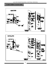
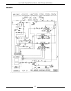
Electric Oven
NOTE:
A combination of terminal numbers and wire
numbers will be used to describe the circuit paths. The
complete path will be described when a component is
energized.
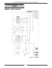
Solid State Control (Elec)
NOTE:
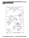
Use ECO2D Schematic
1. Conditions.
A. Fuses are good.
B. Supply voltage to unit (three phase)
1) L1 to power switch: wire #1; J1-1; fuse;
wire #1A and one side of heater contacts
C1: wire #61
2) L2 to one side of heater contacts C2: wire
#62
3) L3 to power switch: wire #2; J1-2; fuse;
wire #2A and one side of heater contacts
C31: wire #64
4) Good chassis ground
C. Power switch "off"
D. Oven at room temperature
E. Solid state control off
F. Door switch closed
G. Fan speed switch in either position
H. Cooldown switch off
J. Timer off
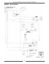
2. Power switch turned "on" (voltage at terminals of
power switch)
A. Power On lamp lights: wire #34/J1; wire
#41/37
B. Control powered: wire #34; wire #33/3; J1-3;
wire #3; door switch; wire #27/4; J1-4; wire
#4/36/35; terminal 8 and 7; terminal 9 (120
VAC) or terminal 10 (200-240 VAC); wire
#39/37
C. Blower motor energized: wire #34; wire #33/3;
J1-3; wire #3; door switch; wire #27/4; J1-4;
wire #4; motor speed switch; wire #11 high or
12 low ); J1-(11 high or 12 low); wire #(11 high
or 12 low); wire #13/7; J1-7; wire #7/37
3. Control set to cook temperature contacts 6/7 close
A. Contactor coil energized: terminal 6; wire
#9; J1-9; wire #9/50; wire #52/7; J1-7;
wire #7/37
B. Heating lamp lights: terminal 6; wire #43;
wire #42/37
4. Heating elements energized
A. L1; wire #61; C1; Wire #70; wire #75; C3; Wire
#64; L3
B. L1; wire #61; C1; Wire #74; wire #71; C2; Wire
#62; L2
5. Oven reaches set temperature and control contacts
6/7 open
A. Power removed from contactor coil
1) Heating elements de-energized
B. Heating lamp goes out.
6. Oven cycles on solid state control until power switch
is moved from the "on" position or the door is
opened.
NOTE:
The blower motor and heating elements are
de-energized when the door is opened and the oven
is in the heat mode.
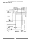
Solid State Timer (Elec)
NOTE:
Use ECO2D Schematic
NOTE:
The timer is not connected to the heating circuit
and will not prevent the oven from heating when time
expires.
1. Power switch on
2. Time dialed into timer, contacts 1/3 close.
A. Timer motor energized: wire #34/64; timer
contacts 1/3; wht wire; wire #37
3. Time expires.
A. Contacts 1/3 open
1) Timer motor de-energized
B. Contacts 1/4 close