


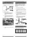

HALF-SIZE CONVECTION OVENS - ELECTRICAL OPERATION
21
6. Temperature is satisfied and control contacts 6/7
open
A. Heat light goes out.
B. Power removed from ignition transformer.
7. Ignition module de-energized
A. Gas valve de-energized, gas supply to burner
off.
8. Oven cycles on solid state control until power switch
is moved from the "on" position or the door is
opened.
NOTE:
The blower motor, heat lamp and gas valve
are de-energized when the door is opened during
the heat mode.
Solid State Timer (Gas)
NOTE:
Use GCO2D Schematic
NOTE:
The timer is not connected to the heating circuit
and will not prevent the oven from heating when time
expires.
1. Power switch on
2. Time dialed into timer, contacts 1/3 close.
A. Timer motor energized: wire #34/64; timer
contacts 1/3; wht wire; wire #37
3. Time expires.
A. Contacts 1/3 open
1) Timer motor de-energized
B. Contacts 1/4 close
4. Buzzer sounds: wire #34/64; timer contacts 1/4; wire
#66; wire #65/37
5. Timer turned to off.
A. Contacts 1/4 open
1) buzzer de-energized
Cooldown (Gas/Solid State Control)
NOTE:
Use GCO2D Schematic
1. Conditions
A. Oven temperature needs to be lowered.
B. Power switch on
2. Cooldown switch on
A. Blower motor energized: power switch; wire
#34/33/36/11; J1-11; wire #11; wire #13/7; J1-
7; wire #7/37; power switch
Electronic Control (Gas)
NOTE:
Use GCO2C Schematic
NOTE:
A combination of terminal numbers and wire
numbers will be used to describe the circuit paths. The
complete path will be described when a component is
energized.
Heat
1. Conditions.
A. Supply voltage to unit.
1) L1 to power/cooldown switch: wire #1;
J1-1; wire #1
2) L2 to:
a. Motor: wire #2; J1-2; wire #2; J1-7;
wire #7/13
b. Primary of ignition transformer: wire
#2; J1-2; wire #2; J1-7; wire #7
c. Primary of control transformer: wire
#2; J1-2; wire #2; J1-7; wire #7/97
3) Good chassis ground: ignition module
transformer
a. Ignition module: GND
b. Electronic control: terminal 8 of
control; J2-8; J1-6; wire #6; GND
c. Gas valve: wire #48; GND
d. Ignition transformer: GND
B. Power/cooldown “off".
C. Oven at room temperature.
D. Door switch closed.
E. Manual gas valve open.
2. Power/cooldown switch turned "on"
A. Control transformer primary powered: wire
#26/4; J1-4; wire #4/94; wire #97/7; J1-7; wire
#2; J1-2; wire #2; L2
3. Control powered from secondary of control
transformer:
A. 6 VAC - wire #16; J1-16; J2-3; J2-2; J1-15;
wire #15
B. 12 VAC - wire #14; J1-14; J2-1; J2-2; J1-15;
wire #15
4. Control set to desired temperature
A. Control verifies heat mode: 16 to 18 VDC
output on J2-11; J1-20; wire #20/21;
power/cooldown switch; contacts of switch are
open and no return voltage to J2-5
B. Control verifies that door is closed: 16 to 18
VDC output on J2-11; J1-20; wire #20/27; door
switch; wire #3; J1-3; J2-4