


VHX SERIES STEAMERS - REMOVAL AND REPLACEMENT OF PARTS
F24700 (October 2001)Page 17 of 68
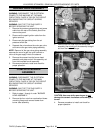
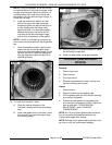
a. From the bottom right side, raise
the boiler two to three inches so
it tilts to the left. When the
remaining water has drained out,
lower the boiler before.
proceeding.
B. Remove the drain/scale clean-out plug
from the bottom of the boiler.
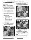
6. Slide the boiler forward and remove it from
base frame.
7. Install a new boiler and secure it to frame.
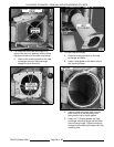
8. Refer to "HEAT EXCHANGER" and perform
steps 13 through 15.
9. Reconnect all steam, water, drain and power
connections and check for proper operation.
BOILER FILL AND COLD WATER
CONDENSER SOLENOID VALVES
WARNING:
DISCONNECT THE ELECTRICAL
POWER TO THE MACHINE AT THE MAIN
CIRCUIT BOX. PLACE A TAG ON THE CIRCUIT
BOX INDICATING THE CIRCUIT IS BEING
SERVICED.
1. Turn off the water supply to the steamer.
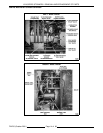
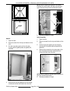
2. Open the cabinet base door and remove the
cover from the pressure switch control box to
access the solenoid valves. Both solenoid
valves are located side by side at the rear of
the box with the boiler fill near the bottom and
the cold water condenser near the middle.
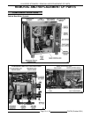
Refer to "CABINET BASE BOILER
CONTROLS" under "COMPONENT
LOCATIONS" in “REMOVAL AND
REPLACEMENT OF PARTS”.
3. Disconnect the power lead wires from the
solenoid valve being serviced.
4. Disconnect the water lines for the valve being
serviced and remove the valve.
5. Reverse procedure to install.
PILOT GAS VALVE
WARNING:
DISCONNECT THE ELECTRICAL
POWER TO THE MACHINE AT THE MAIN
CIRCUIT BOX. PLACE A TAG ON THE CIRCUIT
BOX INDICATING THE CIRCUIT IS BEING
SERVICED.
WARNING:
SHUT OFF THE GAS BEFORE
SERVICING THE UNIT.
WARNING:
ALL GAS JOINTS DISTURBED
DURING SERVICING MUST BE CHECKED FOR
LEAKS. CHECK WITH A SOAP AND WATER
SOLUTION (BUBBLES). DO NOT USE AN OPEN
FLAME.
NOTE:
Gas combination control valves are not
serviceable and should not be disassembled. Once
the problem has been isolated to this component,
replace it. Do not attempt to repair the assembly.
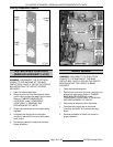
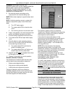
1. Open the cabinet door to access the Pilot gas
valve.
2. Disconnect the lead wires.
3. Remove pilot gas tubing from the top of the
valve (outlet side).
4. Remove the valve from the gas supply piping.
5. Reverse procedure to install and adjust pilot
pressure as outlined under "GAS PILOT
PRESSURE ADJUSTMENT" in "SERVICE
PROCEDURES AND ADJUSTMENTS".
MAIN GAS VALVE
WARNING:
DISCONNECT THE ELECTRICAL
POWER TO THE MACHINE AT THE MAIN
CIRCUIT BOX. PLACE A TAG ON THE CIRCUIT
BOX INDICATING THE CIRCUIT IS BEING
SERVICED.
WARNING:
SHUT OFF THE GAS SUPPLY
BEFORE SERVICING THE UNIT.
WARNING:
ALL GAS JOINTS DISTURBED
DURING SERVICING MUST BE CHECKED FOR
LEAKS. CHECK WITH A SOAP AND WATER
SOLUTION (BUBBLES). DO NOT USE AN OPEN
FLAME.
NOTE:
Gas combination control valves are not
serviceable and should not be disassembled. Once
the problem has been isolated to this component,
replace it. Do not attempt to repair the assembly.
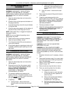
1. Open the cabinet base door to access the main
gas valve.
2. Disconnect the lead wires.
3. Separate the union above the gas valve (outlet
side).
4. Remove the valve from the gas supply piping.
5. Reverse procedure to install and adjust
manifold pressure as outlined under "GAS
MANIFOLD PRESSURE ADJUSTMENT" in
"SERVICE PROCEDURES AND
ADJUSTMENTS".