


VHX SERIES STEAMER - ELECTRICAL OPERATION
F24700 (October 2001) Page 50 of 68
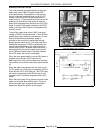
upper and lower set point limits. The
cycling pressure switch continues to
energize and de-energize the heating
circuit to cycle the burner ON and OFF.
This sequence continues until one of the
following occurs:
1) Power switch is turned OFF.
2) Boiler water level drops below the
LLCO probes for the main water level
control and the auxiliary low level cut-
off control
3) Boiler pressurizes to 15 PSI, causing
the high limit pressure switch to
OPEN.
Water Refill (After Initial Fill)
1. Water level drops below low level probe (LL).
A. HL relay is energized.
1) HL N.O. contacts CLOSE, fill
solenoid is energized and HL LED
comes ON.
2. Water reaches LL (low level) probe.
3. Water reaches high level probe.
A. HL relay is de-energized.
1) HL N.O. contacts OPEN, fill solenoid
is de-energized and HL LED goes
out.
4. The water refill cycle will occur whenever the
water level is below the low level probe and will
not affect the operation of either the preheat or
cook cycle.
Boiler Blowdown/Drain
1. Power switch turned OFF.
A. Boiler blowdown sequence starts.
B. The automatic blowdown solenoid valve
(N.O.) is de-energized and valve OPENS
to drain the boiler.
C. Power is removed from all components
except cold water condenser (CWC)
thermostat and solenoid valve. The CWC
thermostat cycles as necessary to lower
the discharge temperature of the water
and condense steam going into the drain.
COOKING COMPARTMENT CONTROLS
1. Conditions.
A. Doors shut (closes the N.O. door switch
contacts).
B. Cooking timers OFF.
C. Compartment pressure switch contacts
OPEN.
2. With boiler at operating pressure.
A. Cooking compartment pressure switch
CLOSES (approx. 3 PSI).
1) Cooking compartment ready light
(green) comes ON.
3. Start a cook cycle.
A. Insert product into steamer and close door.
B. Set a cook time.
NOTE:
On initial startup, if a cooking timer is
set immediately after the ready light comes on,
steam solenoid chattering will be heard (oil
canning) and the ready lights will flash for
several seconds. This condition is caused by
the manifold steam pressure being on the
"fringe" of the pressure switch set point. When
a cook timer is set, the compartment steam
solenoid valve opens causing the manifold
steam pressure to drop, slightly below the
pressure switch set point. At the same time,
steam pressure is still increasing in the boiler.
This opposing condition causes a pressure
"bounce" to occur. After the steam pressure
passes approximately 4 psi this condition
subsides. During normal operation, this
condition will not be seen.
C. Contacts 1/3 of cook timer CLOSE and
timer motor is energized.
1) Compartment steam solenoid valve
energized and steam begins to enter
the compartment.
2) Ready light (green) goes out and
Cooking light (red) comes ON.
NOTE:
Steam should not be seen entering
either compartment until a cook time is
set. This energizes the steam solenoid
valve of the cooking compartment to allow
steam flow.
4. Time expires on timer.
A. Timer contacts 1/3 OPEN, timer motor de-
energized.
B. Steam solenoid valve de-energizes,
stopping the flow steam into compartment.
C. Timer contacts 4/1 CLOSE and energize
buzzer until manually turned OFF.
D. Cooking light (red) goes out and Ready
light (green) comes ON.
5. Timer manually turned OFF.
A. Contacts 1/4 OPEN
B. Alarm Buzzer de-energized and stops
buzzing.
6. Steamer reverts to preheat cycle until time is
dialed on timer and the door is shut, water level
drops below low level cut-off probe or the
power switch is turned OFF.