


VHX SERIES STEAMER - SERVICE PROCEDURES AND ADJUSTMENTS
F24700 (October 2001) Page 26 of 68
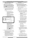
C. Verify LED’s on the water level control
board, HL LED should be off, and LLCO
LED should be illuminated.
3. Open the ball valve in the probe housing
assembly (boiler left side) about half way, to
gradually remove boiler water and activate a fill
cycle.
Do not
press the reset switch to start
the ignition cycle.
The next step requires a
visual sight glass measurement that cannot be
obtained, if there is boiling action in the vessel.
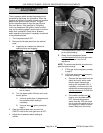
A. Verify water level in the boiler sight glass
drops 1/4" to 3/8" before a fill cycle is
initiated. Repeat at least twice to verify
correct fill.
1) If proper fill wasn’t obtained:
a. Verify probes 50, 51, and 52
have the correct colored wire to
them and to the water level
control board.
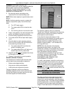
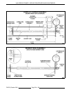
b. Remove the 3 probe assembly,
clean lime scale build-up from
the probes and compare probe
lengths to drawing.
c. Remove 3/8” flex line from the
probe housing assembly to the
boiler and remove any
obstructions. The 1/4"
compression fitting elbow and
1/4" tee into the boiler shell for
the balance tube are sloped 1/8"
so condensation drains into
boiler. When replacing, the
assembly
must
have this slope
to prevent a blockage from
condensate build-up.
4. Test the water level control board LLCO circuit.
A. With the boiler full with water, turn off the
water supply and open the ball valve in the
probe housing assembly.
B. Shortly after the water drops below the
lowest visible level in the sight glass, the
LLCO LED on the water level control
board should turn off, LLCO relay should
de-energize and the normally open
contacts should return there shelf state.
C. Repeat at least twice to verify correct
LLCO operation.
Auxiliary Low level Cut-Off Control
5. Continued testing with focus on the auxiliary
LLCO circuit. With water below the lowest
visible level in the sight glass (below Aux LLCO
probe), and boiler in state of initial fill:
A. Verify Aux LLCO LED is off on the Aux
water level control board.
B. Verify Low Water light is illuminated (front
control panel).
C. Verify 24 volt AC is on Aux LLCO COM,
and 0 volt is on Aux LLCO N.O. contacts.
1) With the water level above the Aux
LLCO probe and in the initial fill state:
a. Verify Aux LLCO LED is
illuminated on the auxiliary low
water board.
b. Verify N2 on the relay board is
illuminated (new style boiler
controls only).
c. Verify the "green" ready light in
the reset switch is illuminated.
d. Verify 24 volt AC is on the Aux
LLCO common and normally
open contacts of the auxiliary
water level control board.
2) With the main gas valve turned off,
water supply valve turned off, and
probe housing assembly ball valve
opened, press the reset switch.
a. Verify low water light (front
control panel).
b. Blower comes on.
c. Gas pilot cycles at
approximately 15 seconds on
and 5 seconds off.
3) Shortly after water level drops below
the lowest visible level in the sight
glass, the Aux LLCO circuit should be
activated.
a. Low water light turns on.
b. Aux LLCO led turns off.
c. Combustion blower is de-
energized.
d. Gas pilot stops cycling.
4) Press reset switch to verify lockout.
5) Disconnect lead wire from Aux LLCO
probe. If there is any measurable
resistance between the probe and the