


VHX SERIES STEAMER - ELECTRICAL OPERATION
F24700 (October 2001)Page 43 of 68
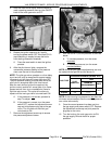
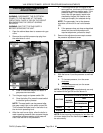
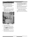
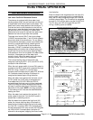
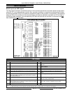
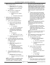
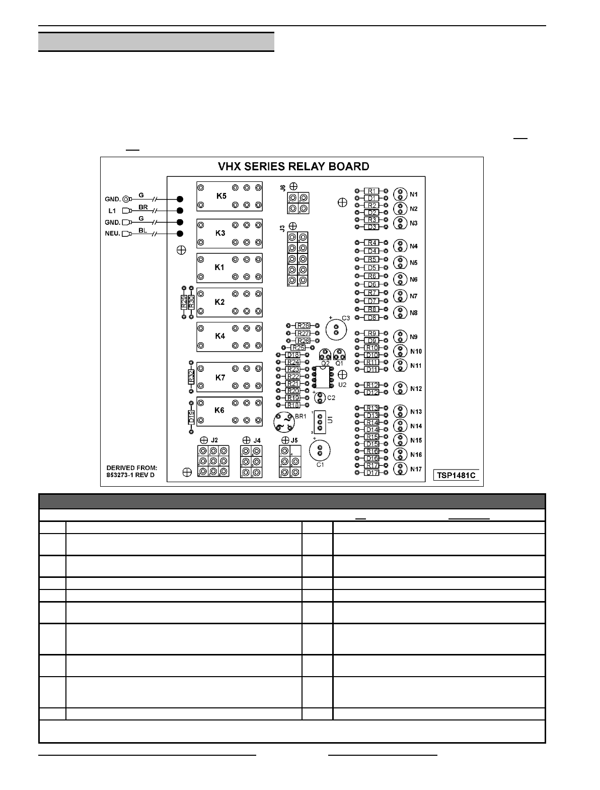
RELAY BOARD
Board Layout and LED Legend
The relay board Provides a centralized location for wire harness connections and power transfer through board
relays (K1-K7) to the other steamer controls. Also, provides a condition or component troubleshooting indicator
by utilizing seventeen LED’S on the board to represent the status of the condition or component in the operating
sequence. When the condition for the component being monitored is satisfied or activated, an LED will light to
indicate its proper operation. If the corresponding LED does not light then the condition or component has not
been satisfied or is not activated.
LED LEGEND
LED ON = Condition satisfied or component activated.
1
LED OFF = Condition not satisfied or component de-activated.
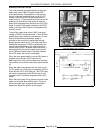
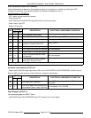
LED DESCRIPTION LED DESCRIPTION
N1 Board powered (24vac). N10 Auxiliary water level satisfied (LLCO) and reset switch
activated.
N2 Auxiliary water level satisfied (LLCO). N11 Boiler operating pressure condition satisfied and reset
switch activated.
N3 High limit pressure switch closed. N12 Combustion blower ON.
N4 Steamer is ready (ready light "green" is ON). N13 Combustion blower air pressure switch satisfied.
N5 Auxiliary water level satisfied (LLCO) and reset switch activated. N14 Ignition module pilot voltage (PV) to board level timing
circuit.
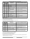
N6
1
Low water condition exists (N2 LED ON) or previously existed. If
water level condition is satisfied and the reset switch is activated
then N6 LED will turn off.
N15
2
Pilot voltage (PV) to pilot gas valve.
N7 Boiler pressure condition satisfied and reset switch activated. N16 Ignition module main voltage (MV) to low water level
contacts (LLCO) on water board.
N8
1
Boiler High pressure condition exists (N3 LED ON) or previously
existed. If boiler pressure condition is satisfied and the reset switch
is activated then N8 led will turn off.
N17 Low water level satisfied (LLCO) and main voltage (MV)
from ignition module is supplied to main gas valve.
N9 Cycling pressure switch CLOSED “call for heat”.
NOTES
: 1. At initial power on, N6 & N8 led’s will be ON until conditions are satisfied and reset switch is activated.
NOTE: 2. Board level timing circuit energized and powers pilot gas valve for approximately 15 seconds then de-energizes.