


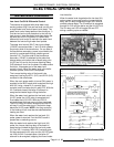

VHX SERIES STEAMER - ELECTRICAL OPERATION
F24700 (October 2001) Page 46 of 68
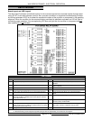
SEQUENCE OF OPERATION
NEW STYLE CONTROLS - BOILER
This sequence of operation is written for boiler
bases with the new style boiler controls. See
"BOILER CONTROL STYLES" under "GENERAL".
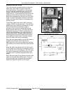
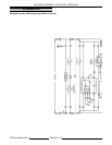
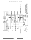
Refer to schematic diagram TSP1480.
Initial Fill and Preheat
Conditions.
A. Power switch OFF.
B. Boiler connected to correct voltage
(120VAC).
C. Boiler properly grounded.
D. Gas and water supply valve(s) ON.
E. Main gas valve manual valve in ON
position
F. Cycling pressure switch closed.
G. High limit pressure switch closed.
H. Cold water condenser (CWC) thermostat
open.
I. Automatic blowdown solenoid valve
(A.B.D.) open and boiler empty.
2. Turn power switch ON.
A. Automatic Blowdown valve (N.O.) is
energized and close.
B. Water level control (WLC) energized.
1) High level (HL) relay energized, HL-3
contacts (N.O.) close.
a. Fill solenoid energized, water
begins filling the boiler (fill time
4-11 min.).
2) HL LED lit.
C. Auxiliary water level control is powered.
1) Aux. LLCO N.O. contacts remain
open.
D. 120VAC to one side of K5(1) N.O., K1(1)
N.O., K3(1) N.O., K4(1) N.O. contacts.
E.
N6 lit.
Low Water light (control panel) lit
thru K3(1) N.C.
F.
N8 lit.
Hi Pressure light (control panel) lit
thru K4(1) N.C.
G.
N1 lit.
24VAC transformer is energized
and relay board is powered.
1) 24VAC to one side of auxiliary water
level control LLCO contacts (N.O.).
2)
N3 lit.
K2 energized through the high
limit pressure switch contacts (N.C.).
a. K2 contacts K2(1) N.O. & K2(2)
N.O. close, no power
transferred.
3)
N9 lit.
24VAC to one side of K3(2)
N.O. contacts through cycling
pressure switch N.C.
3. Water level reaches LLCO probe for both water
level control and auxiliary low level control.
A. LLCO relay on water level board
energizes, LLCO contacts (N.O.) close
1) LED on board lights.
B. Aux. LLCO relay energizes, aux. LLCO
contacts (N.O.) close.
1) LED on board lights.
2)
N2 lit.
K1 is energized.
a. K1(1) N.O. close.
b.
N4 lit.
Ready light (green) on the
control panel manual reset
switch, ON.
3) K1(2) N.O. close.
NOTE:
No power is transferred until manual
reset switch pressed.
NOTE:
The LLCO and aux. LLCO relays will
remain energized and LLCO LED’S will remain
lit until the water level drops below the LLCO
probes or the power switch is turned OFF.
NOTE:
The reset switch could be pressed to
start combustion blower & ignition cycle but it’s
preferred to let the boiler fill the to the "High
Level" before continuing.
4. Water reaches LL (low level) probe.
5. Water reaches HL (high level) probe.
A. Fill solenoid is de-energized.
B. HL-LED
6. Manual reset switch pressed.
A.
N5 lit.
K3 is energized (120VAC).
NOTE:
Relay K3 remains energized through
K3(1) N.O. locking circuit.
1)
N6 goes out
. K3(1) N.O. contacts
close and K3(1) N.C. contacts open.
2) Low water light (control panel) goes
out.
3)
N10 lit.
K3(2) N.O. contacts close.
a. 24VAC to one side of K4(2) N.O.
contacts.
B.
N7 lit.
K4 is energized (120VAC).