


VHX SERIES STEAMERS - OPERATION
F24700 (October 2001) Page 8 of 68
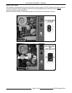
STEAMER OPERATION
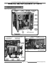
CABINET BASE BOILER
Ensure that all utility connections to the steamer
have been made and are turned ON and that the
knob on the main gas valve is in the ON position.
The VHX Series steamers are CSD-1 compliant and
are equipped with amber colored lights on the boiler
control panel for High Pressure and Low Water level
that illuminate and stay on until the boiler is full and
the manual reset switch pressed.
1. Turn power switch ON.
A. Amber colored lights on the boiler control
panel for High Pressure and Low Water
level will illuminate. and stay on until the
boiler is full and the reset switch is
pressed.
B. Water will begin filling the boiler and the
blowdown solenoid valve will close. The
boiler should fill, in four to eleven minutes.
C. As water fills the boiler, observe water
level gauge glass to verify that water is in
boiler. See "WATER LEVEL GAUGE
ASSEMBLY" in "COMPONENT
FUNCTION” and COMPONENT
LOCATION “ under "REMOVAL AND
REPLACEMENT OF PARTS".
D. Once the water in the boiler reaches the
minimum level, the green ready light on
the boiler control panel will illuminate.
NOTE: If the fill has stopped, one visible inch
of water should be in the gauge glass.
2. Press the reset switch on the boiler control
panel.
A. Low water level safety circuit will be reset
and the Low Water level light (amber) will
turn off.
B. High pressure safety circuit will be reset
and the High Pressure light (amber) will
turn off.
C. Sparking will begin three seconds later to
light the pilot burner.
1) If the pilot burner lights, a signal is
sent back through the ignition cable
indicating the presence of pilot burner
flame and sparking stops.
2) If pilot burner flame is not
established immediately, sparking will
continue for 90 seconds. After that
duration, the ignition control module
will lock out and needs to be reset to
start the pilot and main burner lighting
cycle again.
New Style Controls
- Power to the
Pilot gas valve operates on a "timer"
circuit allowing gas flow to the pilot
for approximately 15 seconds, during
ignition trial, then turns off.
D. Main gas valve opens, burner ignites and
begins to heat the water in the boiler. After
approximately 15 minutes, steam should
be present for cooking product. Observe
that the boiler pressure gauge indicates a
steam pressure of 8-10 psi before the
burner shuts OFF.
3. The cycling pressure switch will maintain steam
pressure in the boiler by cycling the main
burner ON and OFF.
COOKING COMPARTMENT
CONTROLS
When the steam pressure in the cooking
compartment manifold reaches approximately 3 psi,
the cooking compartment pressure switch closes,
suppling power to the other cooking compartment
controls. The ready lights will illuminate and after
approximately one minute, the steam pressure in
the boiler will reach the upper limit of 10 psi. If the
pressure drops below approximately 3 psi, the
pressure switch will open, removing power from the
controls.
NOTE:
On initial startup, if a cooking timer is set
immediately after the ready light comes on, steam
solenoid chattering will be heard (oil canning) and
the ready lights will flash for several seconds. This
condition is caused by the manifold steam pressure
being on the “fringe” of the pressure switch set point.
When a cook timer is set, the compartment steam
solenoid valve opens causing the manifold steam
pressure to drop, slightly below the pressure switch
set point. At the same time, steam pressure is still
increasing in the boiler. This opposing condition
causes a pressure “bounce” to occur. After the
steam pressure passes approximately 4 psi this
condition subsides. During normal operation, this
condition will not be seen.