ELECTRIC COMBI OVEN - REMOVAL AND REPLACEMENT OF PARTS
Page 11 of 68
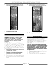
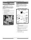
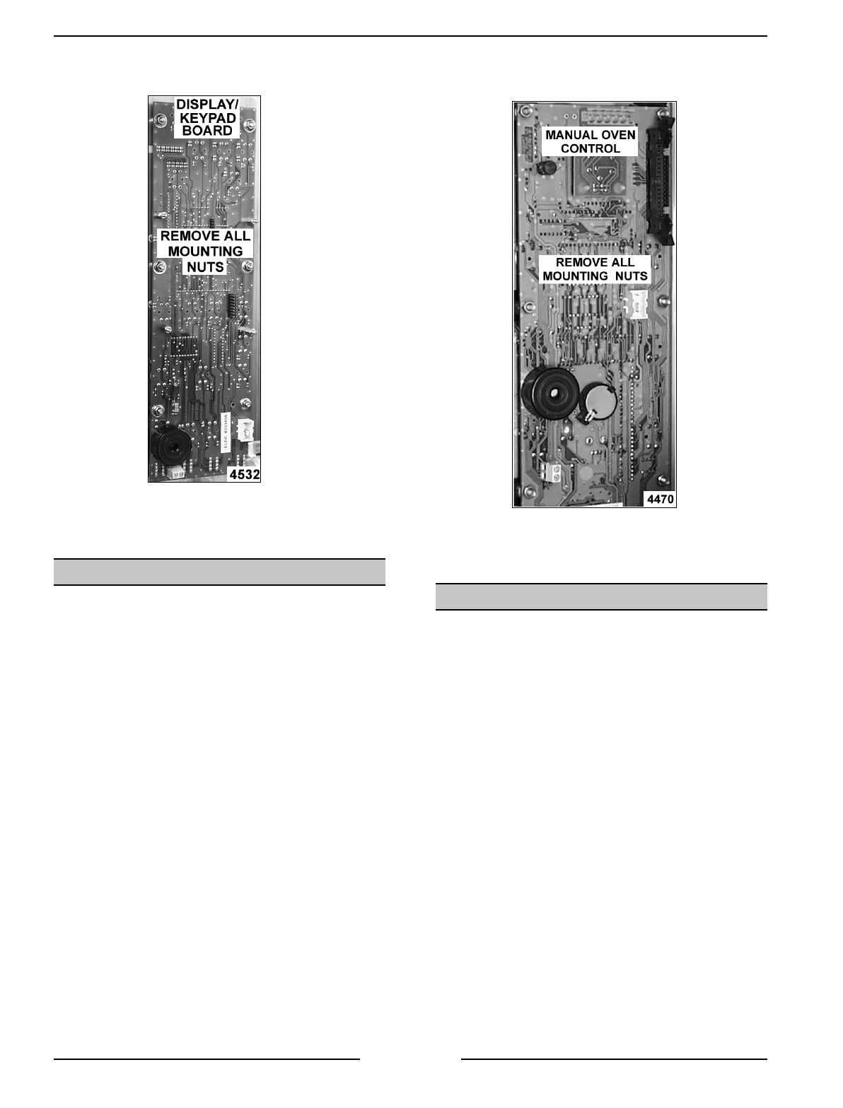
6. Remove the display/keypad board from the
control panel by removing the mounting nuts.
7. Reverse procedure to install.
MANUAL OVEN CONTROLS
WARNING:
DISCONNECT THE ELECTRICAL
POWER TO THE MACHINE AT THE MAIN
CIRCUIT BOX. PLACE A TAG ON THE CIRCUIT
BOX INDICATING THE CIRCUIT IS BEING
SERVICED.
CAUTION: Certain components in this system
are subject to damage by electrostatic discharge
during field repairs. A field service ground kit is
available to prevent damage. The field service
grounding kit must be used anytime the control
board is handled.
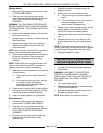
1. Remove the right side panel as outlined under
“COVERS AND PANELS”.
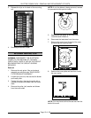
2. Disconnect the ribbon cable, thermocouple
connector, ground leads and door switch
connector from the oven control board.
3. Remove the cover from the oven control board
by removing the mounting nuts at the top and
bottom.
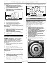
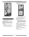
4. Remove the oven control board from the
control panel by removing the mounting nuts.
5. Reverse procedure to install.
RELAY BOARD
WARNING:
DISCONNECT THE ELECTRICAL
POWER TO THE MACHINE AT THE MAIN
CIRCUIT BOX. PLACE A TAG ON THE CIRCUIT
BOX INDICATING THE CIRCUIT IS BEING
SERVICED.
CAUTION: Certain components in this system
are subject to damage by electrostatic discharge
during field repairs. A field service ground kit is
available to prevent damage. The field service
grounding kit must be used anytime the control
board is handled.
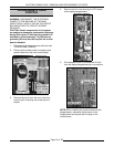
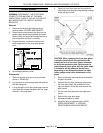
1. Remove the right side panel as outlined under
“COVERS AND PANELS”.
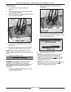
2. Disconnect lead wires from the relay board.


