


ELECTRIC COMBI OVENS - SERVICE PROCEDURES AND ADJUSTMENTS
Page 28 of 68
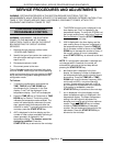
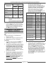
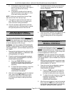
CONVECTION FAN
MOTOR TYPE
CONVECTION FAN MOTOR
VALUE
POSITION 1
(MINIMUM)
POSITION 2
(MAXIMUM)
1 motor Leroy-Somer
(Hanning)
855
1 motor Brook-Crompton
*
860
2 motors Leroy-Somer
(Hanning)
46 120
2 motors Brook-Crompton 30 90
1 motor Leroy-Somer
(Hanning) and 1 motor
Brook-Crompton
38 105
NOTE
: (*) Ovens are shipped from the factory with this
motor and the oven control is configured
accordingly.
The values correspond to the current limits only
and are not the actual current draw of the motor.
11. If all the values have been entered correctly,
press the
START
key to save the configuration
settings and exit the configuration mode. To
review or change a configuration value press
the
TIME
key to return to step 1.
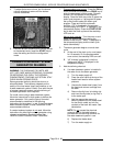
DIAGNOSTIC TEST MODE -
MANUAL CONTROLS
The test mode can be entered only when the oven is
OFF.
The test are performed in a fixed sequence of:
1. Displays and LED’s
2. Selector switch, keypad and adjustment knob.
3. Relays (relay on for max. of 2 seconds).
To Perform:
1. To enter the test mode press the
START
and
TEMP
keys simultaneously for 4 seconds.
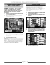
2. The DISPLAY and LED test consists of flashing
all displays and LED’s while the buzzer sounds.
In the temperature display, all the individual
display segments and the word “test” will flash
intermittently. Verify all the displays and LED’s
are flashing. This test will continue until the
START
key is pressed and held for 1 second to
advance to the next step.
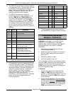
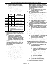
3. The word “test” is displayed in the temperature
display and 10 (start button keypad no.) is
displayed in the “time” display. The KEYPAD
test consists of rotating the selector switch
clockwise
through each position, pressing each
button on the keypad and rotating the
adjustment knob clockwise
then
counterclockwise
to check the functionality of
each.
With each successful selection, the
corresponding number is displayed in the
temperature display. For the adjustment knob,
an upper or lower dash line will be displayed
(depending on rotation). See table below.
Verify that all knob positions and keypad
buttons are functioning properly. When
satisfied, press and hold the
START
key for 4
seconds to advance to the next step.
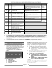
SWITCH/ KEYPAD/KNOB POSITION NO./DASH
LINE
SELECTOR SWITCH OFF 0
SELECTOR SWITCH HOT AIR 1
SELECTOR SWITCH STEAM 2
SELECTOR SWITCH COMBI 3
SELECTOR SWITCH COOL DOWN 4
SELECTOR SWITCH DE-SCALE 5
KEYPAD BUTTON TIME 6
KEYPAD BUTTON PROBE 7*
KEYPAD BUTTON TEMP 8
KEYPAD BUTTON DOOR 9
KEYPAD BUTTON START 10
KEYPAD BUTTON COMBI 12*
KEYPAD BUTTON VENT 13*
ADJUSTMENT KNOB ROTATE CW
“—“
ADJUSTMENT KNOB ROTATE CCW
“—“
NOTE
: Asterisk (
*
) indicates not available on standard
manual controls.
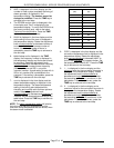
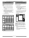
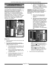
4. The word “test” will still be displayed in the
temperature display. The RELAY test consist of
selecting a particular relay by its code number
(01 to 11) with the adjustment knob and
pressing the
TEMP
key to energize the relay
for a maximum of 2 seconds. See table below.
Verify that each selected relay (K1 to K10) is
functioning. The status of the relay output (0 or
1) will be displayed in the left side of the
temperature display. When satisfied, press and
hold the
START
key for 1 second to advance
to the next step.