


www.vxitech.com
SM7100 Preparation for Use 13
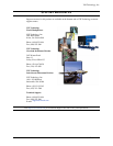
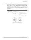
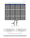
Example 2
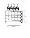
LA
(decimal)
Divide
by 16
MSB LSB
200 200 / 16 = 12 w/ 8 remaining Divide by 16.
= 1100 1000 Convert to MSB and LSB.
= C 8 Convert to hexadecimal. Set the back
switch to C and the front switch to 8.
0
1
2
3
4
5
6
7
8
9
A
B
C
D
E
F
0
1
2
3
4
5
6
7
8
9
A
B
C
D
E
F
BACK FRONT
F
IGURE 2-2: LOGICAL ADDRESS EXAMPLE 2
Here is another way of looking at the conversion: LA = (back switch x 16) + front switch
LA = (1 x 16) + 9
LA = 16 + 9
LA = 25
Set the address switches to FF for dynamic configuration. Upon power-up, the resource manager
will assign a logical address. See Section F - Dynamic Configuration in the VXIbus Specification
for further information.
There is only one logical address per SMIP II base unit. Address assignments for individual
modules are handled through the A24/A32 address space allocation.
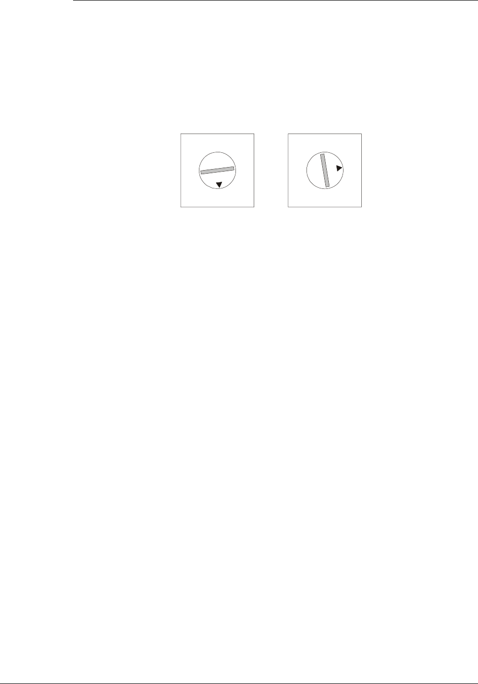
SELECTING THE EXTENDED MEMORY SPACE
The Extended Memory Space of the SMIP II is set by a dip switch that is located on the bottom
edge of the interface card. Position 1, located to the left on the dip switch, selects between A24
and A32 memory address space. In the UP position, the SMIP II will request A24 space. In the
DOWN position, the SMIP II will request A32 space. (Position 2 is not currently used.) The
selection of the address space should be based upon the memory allocation requirements of the
system that the SMIP II module will be installed. The amount of memory allocated to the SMIP II
module is independent of the address space selected.