


www.vxitech.com
SM7100 Programming 23
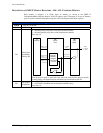
DESCRIPTION OF REGISTERS - A16
The following describes the registers shown in the SMIP II Register Map for A16 address space.
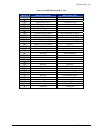
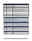
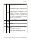
ID Register (0x00) — Read Only
D11-D0 Manufacturer's ID VXI Technology, Inc., set to F4B
16
D13-D12 Address Space
A16/A24
= 00
2
A16/A32 = 01
2
D15-D14 Device Class Extended register based device, set to 01
2
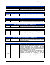
Logical Address Register (0x00) — Write Only
D7-D0 Logical Address
Sets the new logical address in a dynamically configured module.
When set for dynamic configuration (set to FF
16
) a soft reset will not
alter the configured logical address, while a hard reset will set the
register back to FF
16
.
D15-D8 Reserved Writing to this range has no effect.
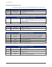
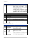
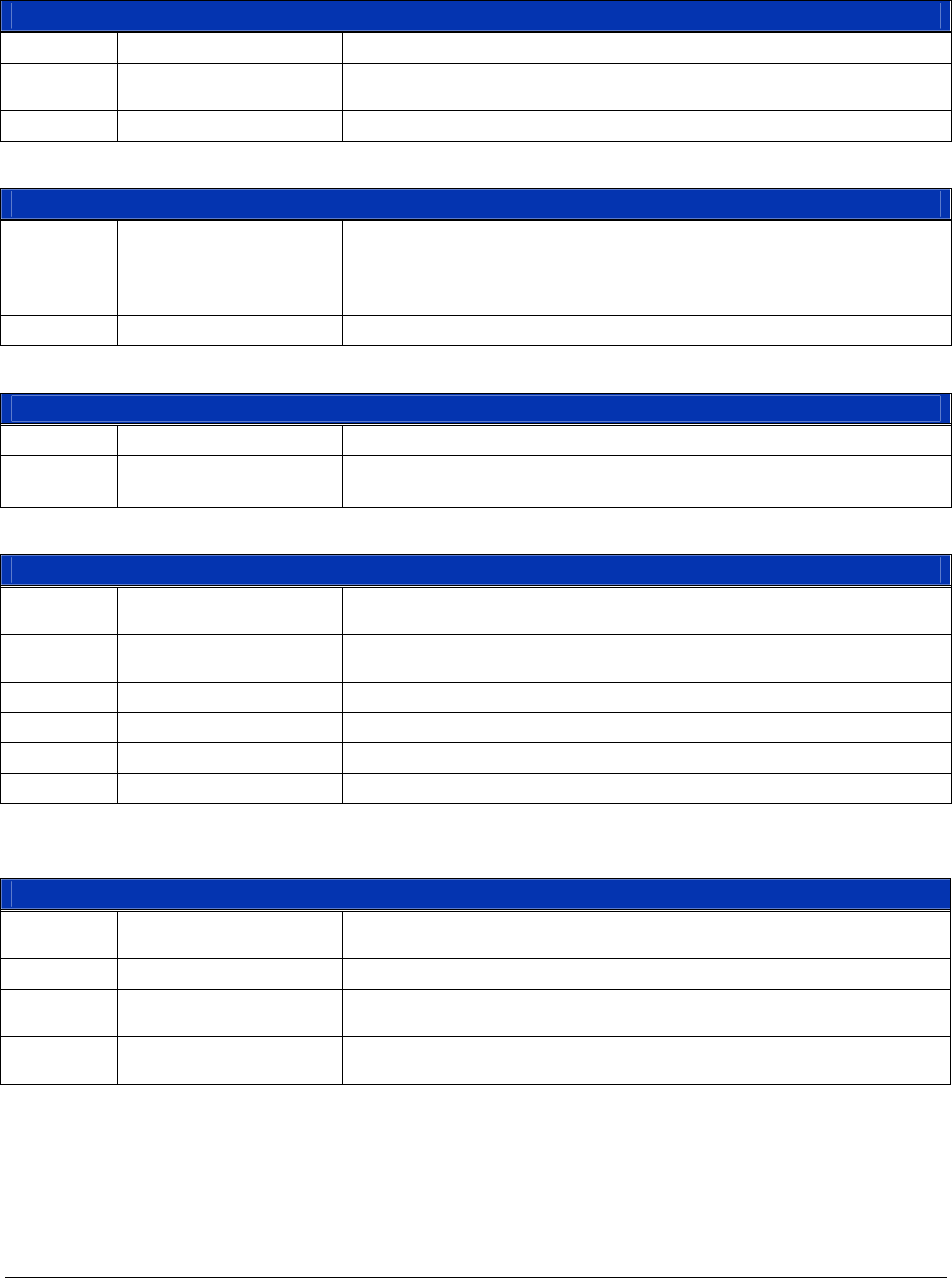
Device Type Register (0x02) — Read Only
D11-D0 Model Code Model 277, set to 115
16
D15-D12 Required Memory
2 Mbytes, set to 2
16
, for A24
2 Mbytes, set to A
16
, for A32
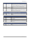
Status Register (0x04) — Read Only
D15 A24/A32 Active
1 = indicates that A24/A32 memory space access is enabled
0 = indicates that A24/A32 memory space access is locked out
D14 MODID*
1 = indicates that the module is not selected by the MODID line
0 = indicates that the module is selected by the MODID line.
D13-D4 Reserved These bits always read as 11,1111,1111
2
D3 Ready This bit always reads as 1
2
D2 Passed This bit always reads as 1
2
D1-D0 Reserved These bits always read as 11
2
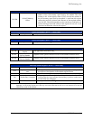
Control Register (0x04) — Write Only
D15 A24/A32 Enable
1 = write a 1 to this bit to enable A24/A32 memory access
0 = to disable access
D14-D2 Reserved Writes to these bits have no effect.
D1 Sysfail Inhibit
Write a 1 to this bit to prevent the module from asserting the
SYSFAIL* line.
D0 Reset
1 = write a 1 to this bit to force the module into a reset state
0 = write a 0 to release the reset state