


VXI Technology, Inc.
26 SM7100 Programming
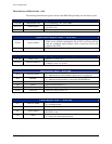
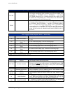
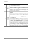
Trace RAM Start High Register (0x28) — Read and Write
D15-D4 Unused Data written to these bits have no effect and always read back as 1.
D3-D0
Sets the four most significant bits of the starting address of the Trace
RAM, allowing the available RAM to be divided into multiple traces.
Trace RAM Start Low Register (0x2A) — Read and Write
D15-D0
Sets the 16 least significant bits of the starting address of the Trace
RAM, allowing the available RAM to be divided into multiple traces.
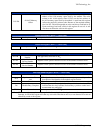
Trace RAM End High Register (0x2C) — Read and Write
D15-D4 Unused Data written to these bits have no effect and always read back as 1.
D3-D0
Sets the four most significant bits of the ending address of the Trace
RAM, allowing the available RAM to be divided into multiple traces.
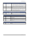
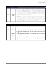
Trace RAM End Low Register (0x2E) — Read and Write
D15-D0
Sets the 16 least significant bits of the ending address of the Trace
RAM, allowing the available RAM to be divided into multiple traces.
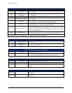
Trace RAM Address HIGH Register (0x30) — Read and Write
D15-D4 Unused Data written to these bits have no effect and always read back as 1.
D3-D0
Sets and reads back the four most significant bits of the current
address of the Trace RAM, allowing the current trace RAM address to
be queried and changed.
Trace RAM Address LOW Register (0x32) — Read and Write
D15-D0
Sets and reads back the sixteen least significant bits of the current
address of the Trace RAM, allowing the current trace RAM address to
be queried and changed.
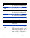
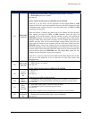
Trace Advance Trigger Select Register (0x34) —Write Only
D15-D8
Sets the TTLTRIG line or lines, which are configured as outputs, and
will toggle when Trace Advance condition occurs in the module. D15
corresponds to TTLTRIG7, D14 to TTLTRIG6, … and D8 to
TTLTRIG0. Setting a bit to a 1 enables the trigger line, setting a bit to
0 disables the corresponding line. All bits are set to 0 when either a
soft or a hard reset is received by the module.
D7-D0
Sets the TTLTRIG line or lines, which are configured as inputs, and
will cause a Trace Advance event to occur in the module. D7
corresponds to TTLTRIG7, D6 to TTLTRIG6, … and D0 to
TTLTRIG0. Setting a bit to a 1 enables the trigger line, setting a bit to
0 disables the corresponding line. All enabled TTLTRIG lines are
OR'd together to allow more than one TTLTRIG line to cause a Trace
Advance event to occur. All bits are set to 0 when the module receives
either a soft or a hard reset.