


www.vxitech.com
SM7100 Module Configuration 15
SECTION 3
SWITCH CONFIGURATION
FRONT PANEL CONNECTION - SM7000
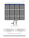
This section details the SM7100 schematics, relays, and pinouts. See Section 4,
Programming, for information on relay addressing.
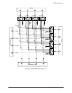
NOTE Although pin numbers between the SM7000 and the HP equivalent
differ, the signals remain in the same location. This makes it possible to
use the same mating connector and cabling for either system. See Table
3-1 and Figure 3-3 for more information on connector J17.
F
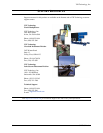
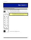
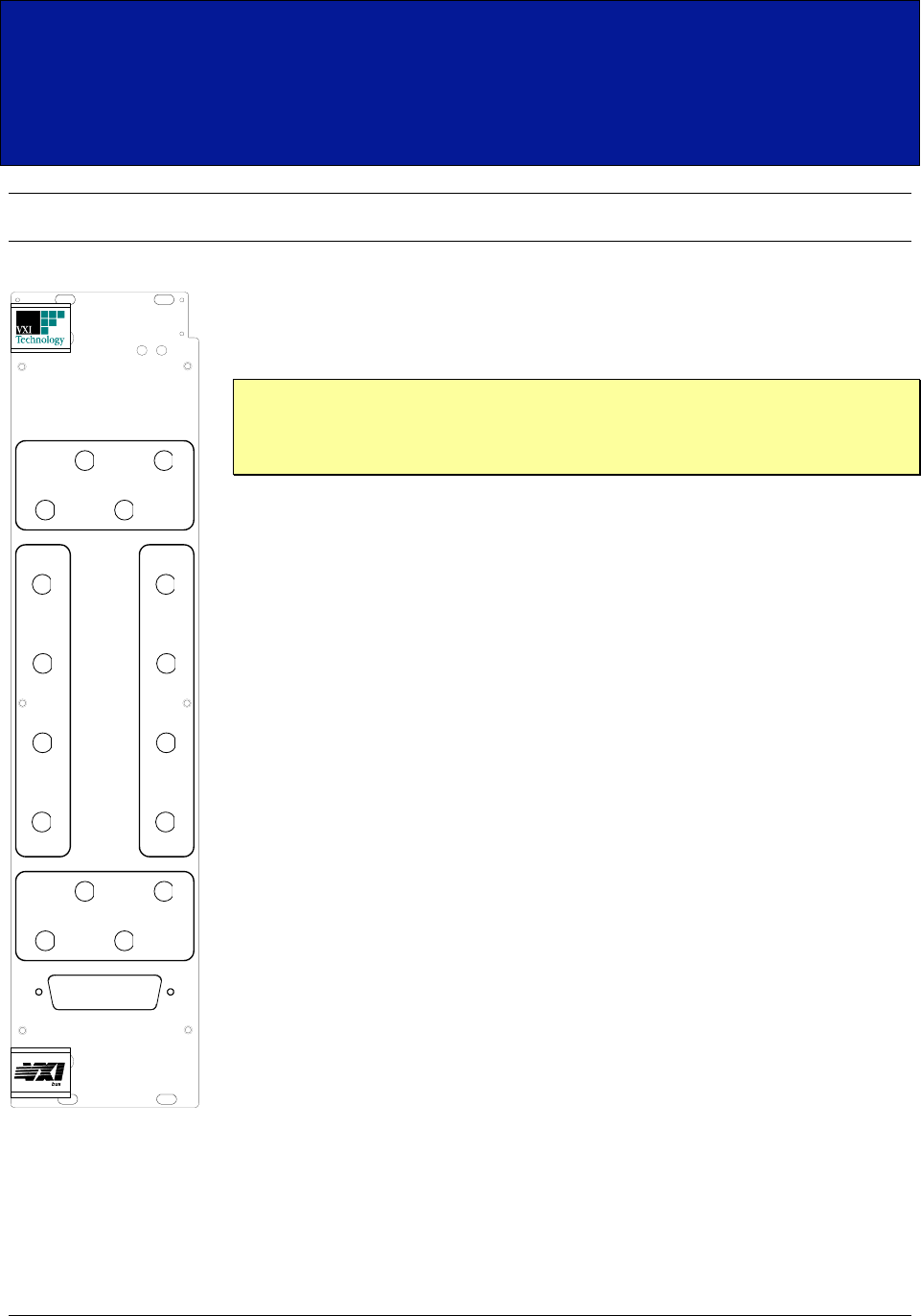
IGURE 3-1FIGURE 3-1 SM7100 FRONT PANEL
ACC/
ERR
PWR/
FAIL
SM7100 EXPANDABLE
MICROWAVE SWITCH MATRIX
INPUTS
1
2
3
4
EXPANSION OUTPUTS
1
2
3
4
EXP INPUTS
1
2
3
4
OUTPUTS
1
2
3
4
EXTERNAL DRIVE