


www.vxitech.com
SM7100 Programming 27
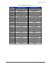
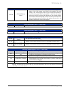
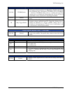
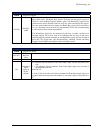
Open Trigger Select Register (0x36) —Write Only
D15-D8
Sets the TTLTRIG line or lines, which are configures as outputs, and
will toggle when Relay Open condition occurs in the module. D15
corresponds to TTLTRIG7, D14 to TTLTRIG6, … and D8 to
TTLTRIG0. Setting a bit to a 1 enables the trigger line, setting a bit to
0 disables the corresponding line. All bits are set to 0 when either a
soft or a hard reset is received by the module.
D7-D0
Sets the TTLTRIG line or lines, which are configured as inputs, and
will cause a Relay Open event to occur in the module. D7 corresponds
to TTLTRIG7, D6 to TTLTRIG6, … and D0 to TTLTRIG0. Setting a
bit to a 1 enables the trigger line, setting a bit to 0 disables the
corresponding line. All enabled TTLTRIG lines are OR'd together to
allow more than one TTLTRIG line to cause a Relay Open event to
occur. All bits are set to 0 when the module receives either a soft or a
hard reset.
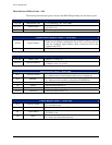
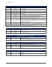
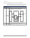
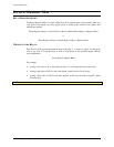
TTL Trigger Polarity Register (0x38) —Write Only
D15-D9 Unused Data written to these bits have no effect.
D8 FAIL LED Control
0 = off
1 = on
D4
Board Busy Trigger
Slope
0 acts on the falling edge, 1 acts on the rising edge.
D3 Relay Open Input Slope 0 acts on the falling edge, 1 acts on the rising edge.
D2
Relay Open Output
Slope
0 sets the falling edge active, 1 sets the rising edge active.
D1
Trace Advance Input
Slope
0 advances on the falling edge, 1 advances on the rising edge.
D0
Trace Advance Output
Slope
0 sets the falling edge active, 1 sets the rising edge active.
Note: A hard or a soft reset sets D3 - D0 to 0.
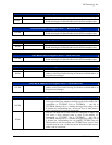
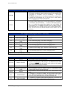
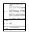
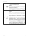
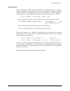
Trace RAM Control Register (0x3A) — Read and Write
D15-D11 Unused Data written to these bits have no effect.
D15-D10 Modules Installed
Set to 0 if the module is installed or set to a 1 if not installed. These
bits are set to 0 at power on. By setting a 1, the SMIP II Interface PCB
will generate DTACK for any read or write cycles to the memory
space of the uninstalled plug-in module.
D9-D5 Unused Data written to these bits have no effect.
D4
Modules used in trace
mode
D9 is for module 5, D4 is for module 0. Set to 1 if the module is used
in trace mode, set to 0 if not in trace mode.
D3-D2 Unused
Data written to these bits have no effect. The value written is read
back.
D1 LOOP ENABLE
1 = Enabled, 0 = Disabled. If enabled, the trace resumes at the start of
active RAM and continues from there. If disabled, the trace stops at
the end of active RAM and clears the TRACE ENABLE bit.
D0 TRACE ENABLE
1 = enabled, 0 = disabled. If the LOOP ENABLE bit is set and the end
of active trace RAM is reached, this bit will not be reset.