


VXI Technology, Inc.
28 SM7100 Programming
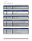
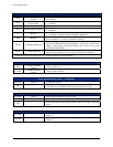
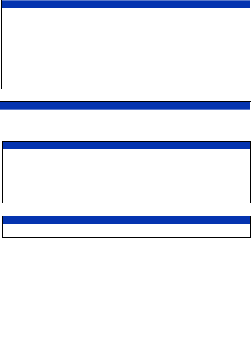
Busy Trigger Control Register (0x3C) — Read and Write
D15-D8 TTLTRIG Select
Sets the TTLTRIG Line or Lines, which are configured as outputs, and
will toggle at the de-assertion of a Board Busy condition sent by the
plug-in modules. D15 corresponds to TTLTRIG7, D14 to TTLTRIG6,
… and D8 to TTLTRIG0. Setting a bit to a 1 enables the trigger line,
setting a bit to a 0 disables the corresponding line. All bits are set to 0
when either a soft or a hard reset is received by the module.
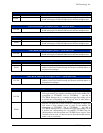
D7-D1 Unused
Data written to these bits have no effect. The value written is read
back.
D0 Busy Trigger Enable
Enables the Board Busy signal received from the switch module to
generate a trigger condition on the TTL Trigger Bus. Setting a bit to 1
enables the generation of a Trigger condition, setting a bit to a 0
disables the corresponding line. This bit is set to 0 when either a soft
or a hard reset is received by the module.
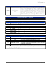
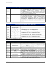
Trigger Advance Register (0x3E) — Write Only
D15-D0 Unused
The act of writing to this location causes a Trace Advance event to
occur in the module. The specific data written to these bits has no
effect.
Board Busy Register (0x3E) — Read Only
D15-D7 Unused These bits always read back as 1.
D6
Indicates whether the SMIP II platform is a single or double wide.
0 = single wide
1 = double wide
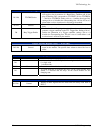
D5-D1 Unused Data written to these bits have no effect.
D0
A 0 read from this bit indicates the relays on the switch module have
settled, a 1 indicates that the relays on the switch module are still
changing state.
Reserved Registers — Read and Write
D15-D0 Unused
Writing to these registers has no effect and will always read back as
FFFF
16
.