


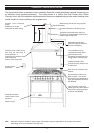
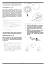
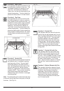

A stability bracket must be fitted behind the appli-
ance and connected to the stability chain connect-
ed to the back panel, as demonstrated in Fig. 5.
GAS CONNECTION - LPG
This appliance should be connected using a
O8mm metal hose that complies with IS 813 and
the connection made to the gas connection pipe
either on the left or right side of the appliance,
using clamps. When connecting to an LPG cylin-
der, the cylinder must be equipped with a pressure
reducer capable of supplying gas at the specified
pressure and should always follow the following
rules:
* The gas connection hose must not be longer
than 1 meter.
* The pressure reducer connection must face
towards the outside of the cooker.
* The hose must not touch any hot surfaces on
the cooker or be routed behind the appliance.
* The location of the gas cylinder should be in
accordance with IS 813 & EN30-1-1.
When replacing empty cylinders, the hose should
not be pulled out of position.
The gas cylinder tap should always be turned off
after use and the gas hose inspected periodically.
CONVERTING FOR LPG USE
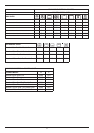
Note: A complete set of LPG injectors are supplied
in the main oven. When configuring the appliance
for use with LPG, the following procedure should
be carried out:
1. Disconnect the appliance from the electrical
supply and shut off the mains gas supply to the
appliance.
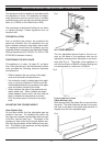
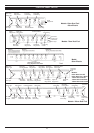
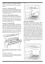
2. Replace the burner injectors by removing the
burner flame cap cover, the burner cap and
unscrewing the injector using a suitable span-
ner. Refer to the Technical Section & Features
section to ascertain the relevant injector sizes
for each burner. (See Fig.6)
12
Fig 7
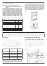
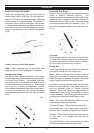
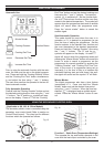
3. Regulate the low flame setting for each burner
using the following procedure:
a. Ignite the burner and leave it in operation
on the high flame setting for one minute.
b. Turn the knob to the low flame setting.
c. Remove the knob by pulling it off the tap
shaft.
d. Using a No.2 flat-head screwdriver, adjust
the low flame setting (anticlockwise to
reduce the rate and clockwise to increase)
as shown in Fig.7. Replace the knob on the
tap shaft.
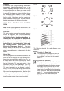
Fig.6
Burner Cap
Burner Flame
Cap Cover
Injector