


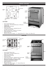
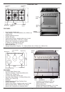
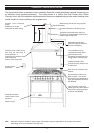
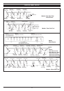

The figure below shows a standard cooker installation fitted with a steel splashback (optional accessory) and
an extraction hood (optional accessory). The model shown is a 100cm Dual Fuel Cooker with a 90cm
Chimney Hood, with the installation requirements and dimensions detailed being similar when installing other
cooker models or when installing a box or glass hood.
9
Extractor Hood Electrical
Supply:
Standard 3 pin socket
located behind steel ducting.
O 125mm Extraction pipe through wall.
O 125mm Flexible Extraction Pipe (not
supplied) connected between extractor flue
outlet & pipe through wall.
Extendable steel ducting
[Minimum height of 450mm to
maximum of 860mm]
The metal filters can be
replaced with carbon filters
(optional extras) thus
eliminating the requirement for
the O 125mm Extraction pipe.
Splashback fixed to wall
through two fixing holes on top
& bottom lips.
Back Trim not on Electric Hob
Models.
Gas connection made on top
RHS of cooker. This can be
moved to the top LHS (Refer to
Fig.5) [Not applicable to Electric
Hob Models]
Gas connection made using
flexible gas line to allow ease of
removal of unit [Not applicable
to Electric Hob Models]
Extractor Hood is fitted to the
wall using the rawl plugs &
screws provided. A
template on the extractor hood
carton details the
position of the fixing holes.
32 Amp Cooker
Switch Box.
Electrical Connection
made on back LHS of
appliance.
(Refer to Fig.4)
300 -
700
260- 280
750
200 -
700
Steel Ducting fixed to wall using supplied
bracket
Note: Dimension ranges for position of power supply and extraction pipe are applicable for all extractor hood models
when fitting the unit in a standard 8 foot high room.
STANDARD COOKER INSTALLATION