


8
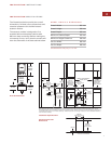
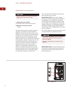
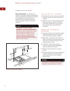
MULTIPLE COOKTOP INSTALLATION
I
MPORTANT NOTE:
I
f the steamer module is
to be used with a combination of additional
cooktop units or modules with a filler strip,
t
he cut-out width is calculated by adding the
corresponding units' cut-out dimensions plus
32 mm for each additional unit.
When multiple units are installed side by side,
each unit must have its own separate recom-
mended electrical circuit.
When two or more modules are installed
together, an integrated module filler strip
(IFILLER/S) is recommended. Contact your
Wolf dealer for information on accessories.
IMPORTANT NOTE:
Review specific
installation instructions for product to product
capabilities.
WOLF STEAMER MODULE
INSTALLATION SPECIFICATIONS
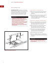
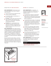
DRAIN CONNECTION
I
MPORTANT NOTE:
T
he steamer module
must be installed with a drain connection and
access to the drain through the base cabinet.
For the drain connection, the 16 mm outlet
from the valve will accept a drain hose that
must flow downward to and tie into an
existing sink drain, or a separate drain with a
freefall may be installed. Following local
building codes; your plumber will dictate how
to plumb the unit. As a third option, the
consumer will supply a heat resistant bucket
for drainage in the location of the drain outlet.
Refer to the illustration on page 7 for location
of the drain outlet.
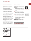
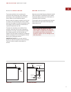
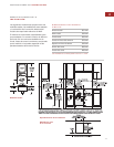
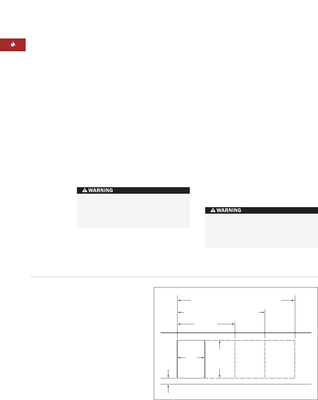
64 mm
min
FRONT OF COUNTERTOP
489 mm
CUT-OUT
DEPTH
743 mm
TWO MODULES WIDTH
1130 mm
THREE MODULES WIDTH OR
1124 mm
/762 mm COOKTOP AND ONE MODULE
1518 mm
FOUR MODULES WIDTH OR
1511 mm
/762 mm COOKTOP AND TWO MODULES OR
1276 mm
/914 mm COOKTOP AND ONE MODULE
356
mm
CUT-OUT
WIDTH
Countertop cut-out dimensions for installation of multiple cooktops
This steamer module must be installed
at least 381 mm away from a Wolf fryer
module, as contact between water and hot
oil may cause burns from steam and hot oil.
If there is no fixed drain connection, use a
heat-resistant receptacle with a minimum
7.6 L capacity. The doors of the base
cabinet must be locked.