


10
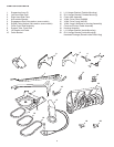
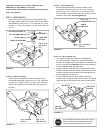
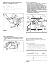
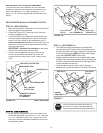
ATTACH CLUTCH IDLER ASSEMBLY TO TRACTOR
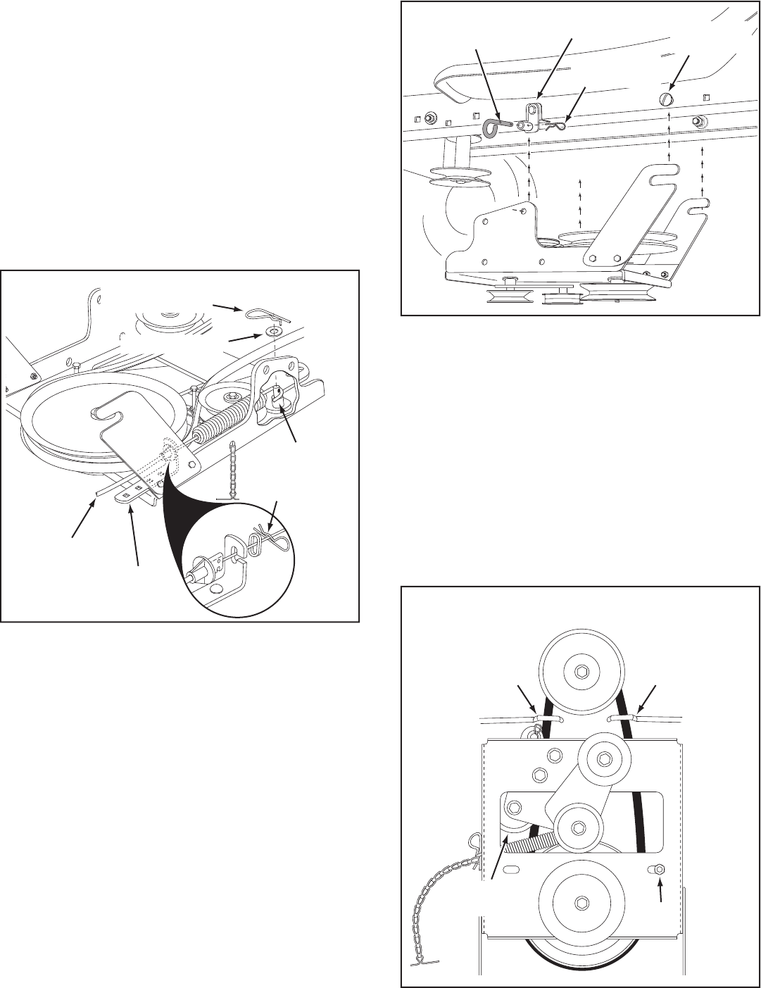
STEP 12: (SEE FIGURE 12)
•
Attach the clutch/idler assembly to the tractor frame.
Hook the notched suspension arms onto the two
shoulder bolts (M) assembled to the outside of the
tractor frame. Lift the front of the assembly and attach
it to the R.H. and L.H. hanger brackets using two pivot
lock pins (GG) and 1/8" hairpin cotters (EE).
PIVOT LOCK PIN (GG)
(use this hole)
SHOULDER
BOLT (M)
1/8" HAIRPIN
COTTER (EE)
L.H. HANGER
BRACKET
FIGURE 12 VIEWED FROM LEFT SIDE
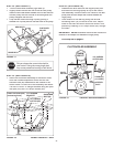
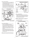
STEP 13: (SEE FIGURE 13)
•
Assemble the drive belt onto the engine pulley fi rst
and then onto the large pulley on top of the clutch/
idler assembly. The belt must be placed inside the
engine pulley belt keeper(s) and between the large
pulley and the keeper bolt next to it.
IMPORTANT:
Do Not
assemble the "V" belt outside of
the engine pulley keepers or outside of the keeper bolt
next to the large pulley.
•
Go to step 48 on page 21.
FIGURE 13 VIEWED FROM UNDERNEATH
ENGINE
PULLEY
ENGINE
PULLEY
Left Side
of Tractor
ENGINE
PULLEY
KEEPER
ENGINE
PULLEY
KEEPER
KEEPER BOLT
IDLER
PULLEY
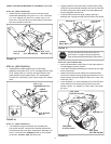
CLUTCH/IDLER ASSEMBLY
FIGURE 11
5/64" HAIR
COTTER PIN
SPACER
1/4" WASHER
TRACTOR'S
CLUTCH CABLE
CABLE
BRACKET
GROOVE
5/64" HAIR
COTTER PIN (DD)
1/4" WASHER (P)
SPACER (LL)
TRACTOR'S
CLUTCH CABLE
CABLE
BRACKET
5/64" HAIR
COTTER PIN (DD)
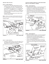
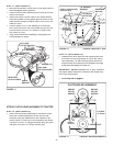
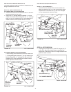
STEP 11: (SEE FIGURE 11)
•
Move the attachment clutch lever on the dash panel to
the disengaged (down) position.
•
Place the clutch/idler assembly on the fl oor on the left
side of the tractor.
•
Attach the tractor's clutch cable to the cable bracket.
Secure the cable housing guide (groove down) to the
cable bracket using the original collar and a 5/64" hair
cotter pin (DD).
•
Place a spacer (LL) on the welded pin on the idler
arm. Hook the end of the clutch cable spring over the
pin and secure it with a 1/4" washer (P) and a 5/64"
hair cotter pin (DD).
• Align cable bracket with welded pin and tighten the
nut assembled in step 9.