


20
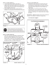
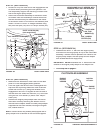
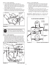
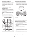
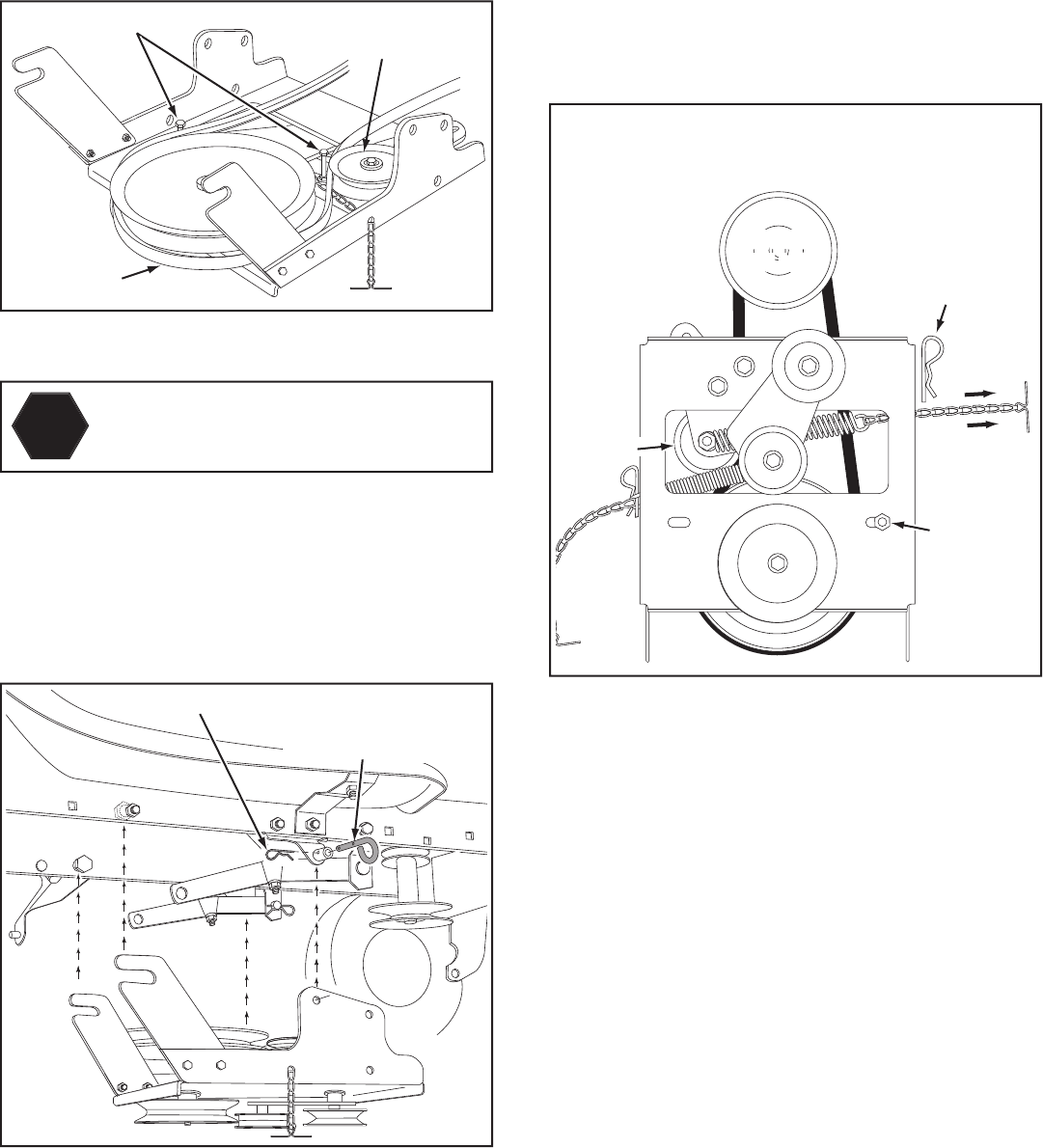
FIGURE 46 VIEWED FROM UNDERNEATH
1/8" HAIRPIN
COTTER (EE)
ENGINE
PULLEY
ENGINE
PULLEY
Left Side
of Tractor
KEEPER
BOLT
IDLER
PULLEY
STEP 47: (SEE FIGURE 46)
•
Assemble the drive belt onto the engine pulley and
then onto the large pulley on top of the clutch/idler
assembly. The belt must be placed to the inside of
the idler pulley and the keeper bolt located beside the
large pulley.
•
Place tension on the belt by pulling the left side
tensioning chain out as far as the 3/32" hairpin cotter
(FF) will allow. Secure the chain in this position by
inserting a 1/8" hairpin cotter (EE) through the chain.
IMPORTANT:
Do Not
assemble the "V" belt around the
outside of the engine pulley keeper or the keeper bolt.
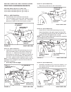
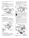
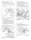
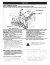
STEP 46: (SEE FIGURE 45)
•
Attach the clutch/idler assembly to the tractor frame
as follows. Hook the assembly's notched arms onto
the two shoulder bolts you assembled to the inside
of the tractor frame. Lift the front of the assembly and
attach it to the R.H. and L.H. hanger brackets using
two pivot lock pins (GG) and 1/8" hairpin cotters (EE).
FIGURE 45 RIGHT SIDE VIEW
PIVOT LOCK PIN (GG)
(use second hole)
1/8" HAIRPIN COTTER (EE)
CLUTCH/IDLER ASSEMBLY
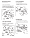
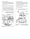
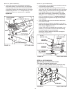
HEX BOLTS
DRIVE BELT
FLAT IDLER
PULLEY
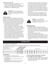
FIGURE 44
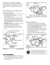
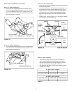
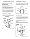
STOP
Did you choose the correct drive belt for
your tractor? Using the wrong length belt
may cause premature bearing or belt failure.
STEP 45: (SEE FIGURE 44)
• Turn the clutch/idler assembly right side up.
•
Slightly loosen the hex bolt next to the fl at idler pulley.
Install the drive belt down between the hex bolt and the
fl at idler pulley with the fl at side of the belt against the
pulley. Retighten the hex bolt.
•
Loop the belt around the large v-pulley, placing it
between the v-pulley and the hex bolt next to the pulley.
Place the belt to the inside of the other fl at idler pulley.