


16
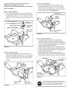
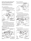
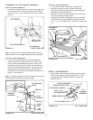
FIGURE 33 RIGHT SIDE VIEW
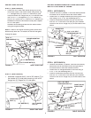
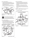
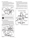
FIGURE 32 RIGHT SIDE VIEW
PIVOT LOCK PIN (GG)
(use second hole)
1/8" HAIRPIN COTTER (EE)
ENGAGEMENT
ROD
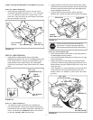
STEP 33: (SEE FIGURE 33)
•
Make sure the attachment clutch lever on the dash
panel is in the disengaged (down) position.
•
Pivot the upper idler arm so that it rests against the
stop bolt and is pointing toward the front as shown.
Screw the trunnion (CC) along the threads of the
engagement rod until it is aligned at the front end of
the idler arm slot. Attach the trunnion (CC) to the slot
using the 3/8" thin washer (S) and a 5/64" hairpin
cotter (DD).
•
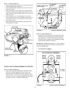
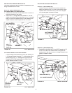
Remove the engine pulley keeper from the side of
the tractor frame by removing the washer and nut
that secure the keeper. Attach the new pulley keeper
supplied with the snow thrower, reusing the original
bolt, washer and nut.
NOTE:
Some tractors may already be equipped with a
pulley keeper that is identical to the new one supplied.
IDLER ARM
5/64" HAIRPIN
COTTER (DD)
TRUNNION (CC)
STOP BOLT
3/8" THIN
WASHER (S)
NEW ENGINE PULLEY KEEPER WITH
ORIGINAL BOLT, NUT AND WASHER
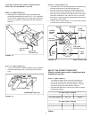
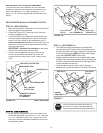
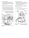
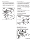
STEP 34: (SEE FIGURE 34)
•
Assemble the short "V" belt onto the engine pulley
and then onto the large pulley on top of the clutch/idler
assembly. The belt must be placed to the inside of the
engine pulley keeper, the idler pulley and the keeper
bolt located beside the large pulley.
IMPORTANT:
Do Not
assemble the "V" belt around the
outside of the engine pulley keeper or the keeper bolt.
•
Go to step 48 on page 21.
FIGURE 34 VIEWED FROM UNDERNEATH
ENGINE
PULLEY
KEEPER BOLT
IDLER
PULLEY
ENGINE
PULLEY
KEEPER
Left Side
of Tractor
CLUTCH/IDLER ASSEMBLY
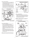
STEP 32: (SEE FIGURE 32)
•
Be sure to lift up the front end of the engagement rod
as shown when performing the next operation. You
can temporarily support the rod using a rubber band
tied to the engine pulley keeper.
•
Attach the clutch/idler assembly to the tractor frame
as follows. Hook the assembly's notched arms onto
the two shoulder bolts you assembled to the inside
of the tractor frame. Lift the front of the assembly and
attach it to the R.H. and L.H. hanger brackets using
two pivot lock pins (GG) and 1/8" hairpin cotters (EE).