


24
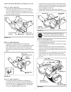
INSTALLING THE ATTACHMENT PIN
STEP 58: (REFER BACK TO FIGURE 54 ON PAGE 23)
•
Lift the front of the snow blower to align the holes in
the mounting plates and the side plates. From the left
side of the tractor insert the attachment pin through
the holes. Secure it with by reinstalling the 1/8" hairpin
cotter (EE).
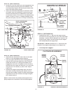
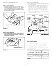
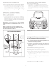
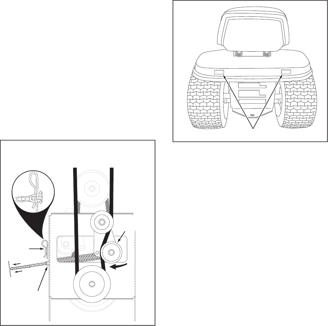
SETTING THE AUGER BELT TENSION
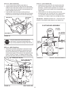
STEP 59: (SEE FIGURE 57)
•
Pull the tensioning chain until the end of the spring is
pulled through the hole in the side of the Clutch/Idler
assembly. Install the 1/8" hairpin cotter (EE) through
the end of the spring, securing it on the outside of the
Clutch/Idler assembly.
IMPORTANT:
For correct belt tension,
the 1/8" hairpin
cotter must attach to the end of the spring
, not to the
chain.
NOTE;
To prevent the chain from dragging on the
ground, loop the end of the chain though the pivot lock
pin. Refer to fi gure 45 on page 20.
FIGURE 57 VIEWED FROM UNDERNEATH
END OF
SPRING
1/8"
HAIRPIN
COTTER (EE)
LEFT SIDE
OF
TRACTOR
FLAT
PULLEY
CLUTCH/IDLER ASSEMBLY
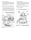
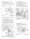
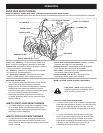
REAR REFLECTORS (KK)
ATTACH REFLECTORS TO REAR FENDER
STEP 59: (SEE FIGURE 58)
•
If your tractor is not equipped with rear refl ectors,
assemble the supplied rear refl ectors (KK) to the rear
fender. Place the refl ectors as close to the bottom of
the fender and as far apart as the shape of the fender
will allow.
FIGURE 58
CHECKLIST
Before you operate your snow thrower, please review the
following checklist to help ensure that you will obtain
the best performance from your snow thrower.
1. All assembly instructions have been completed with all
bolts and nuts properly tightened.
2. Check the engine belt and the auger belt. Make sure
they are routed properly around pulleys and inside all
belt keepers.
3. Check discharge chute for proper rotation.
4. Check operation of tilt control for upper chute.
5. Verify that the lift handle will lock into and release from
the raised transport position. (Refer to the Service and
Adjustments section.)
6. Check skid shoe adjustment. (Refer to the Service and
Adjustments section.)
Operating instructions begin on page 25.