


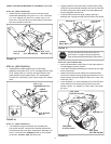
14
FIGURE 28 RIGHT SIDE VIEW
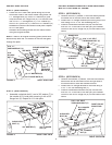
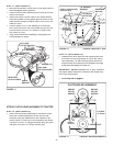
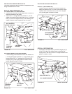
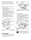
INSTALLING HANGER BRACKETS
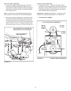
For better clearance, lower the tractor's suspension arms
using the attachment lift lever.
STEP 26: (SEE FIGURE 25 or 26)
On Tractors With Foot Rest Brackets
•
Remove the bolt and nut that fasten the L.H. and R.H.
foot rest brackets to the frame.
•
Attach the L.H. Hanger Bracket (marked "L") to the
inside of the tractor frame using two 3/8" x 1" carriage
bolts (G) and 3/8" fl anged nuts (X). Bolt heads go on
inside of tractor frame. Repeat for the R.H. side.
FIGURE 26 LEFT SIDE VIEW
FIGURE 25 LEFT SIDE VIEW
On Tractors Without Foot Rest Brackets
•
Find the empty hole beneath the foot rest. Attach the
L.H. Hanger Bracket (marked "L") to the inside of the
frame using a 3/8" x 1" carriage bolt (G) and a 3/8"
fl anged nut (X). Bolt head goes on inside of tractor
frame. Repeat for the R.H. side.
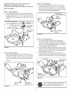
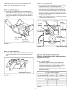
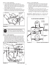
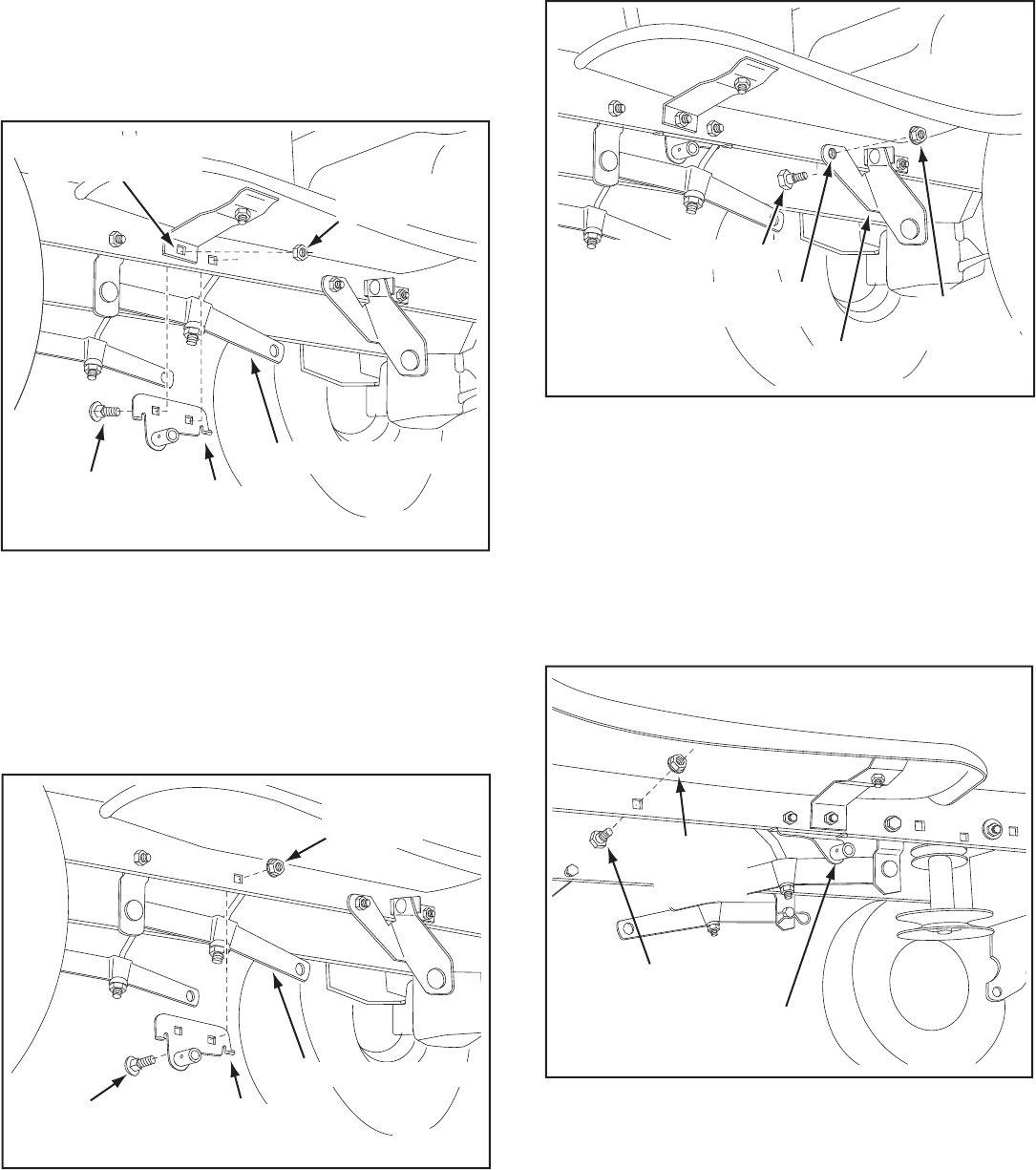
STEP 28: (SEE FIGURE 28)
•
Assemble a shoulder bolt (L) and 3/8" fl anged nut (X)
to the R.H. side of the tractor frame, using the fi rst
empty hole to the rear of the R.H. hanger bracket. Bolt
goes on inside of frame.
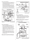
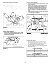
FIGURE 27 LEFT SIDE VIEW
INSTALLING SHOULDER BOLTS
STEP 27: (SEE FIGURE 27)
•
Remove the bolt, washer and nut which fasten the
sway bar bracket to the L.H. side of the tractor frame.
Replace with a shoulder bolt (L) and a 3/8" fl anged
nut (X). Bolt goes on inside of frame.
BOLT REMOVED
FROM THIS HOLE
SWAY BAR
BRACKET
SHOULDER BOLT (L)
3/8"
FLANGED
NUT (X)
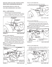
3/8" x 1"
CARRIAGE
BOLT (G)
3/8" FLANGED
NUT (X)
L.H. HANGER
BRACKET
SUSPENSION ARM
SHOULDER BOLT (L)
3/8"
FLANGED
NUT (X)
R.H. HANGER BRACKET
BOLT REMOVED
FROM THIS HOLE
3/8" x 1"
CARRIAGE
BOLT (G)
3/8" FLANGED
NUT (X)
L.H. HANGER
BRACKET
SUSPENSION ARM