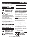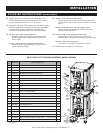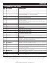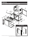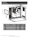
S TA C K IN G I NS T RU C TI O NS
A rotisserie can be stacked with another rotisserie or can
be stacked on top of a matching holding cabinet.
Stacking hardware is required for all stacking combinations
(SEE ABOVE AND THE OPTIONS LIST ON PG 8 FOR MORE INFORMATION).
All fastening holes have been prepunched. The stacking
combination also requires the minimum clearance of
6" (152mm) at the top, back and both sides.
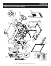
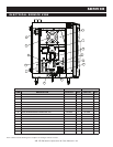
NOTE: Do note remove corner panels. They are not
shown in the drawing only to increase visibility of
the interior components.
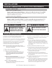
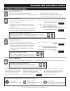
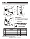
1. Remove the access panels of both units.
2.
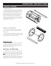
208-240V, 1PH - RH/LH DOOR SWING:
Remove power cord, strain relief bushing, and
strain relief washer (drill out 2 rivets) from the
rotisserie intended to be on the top. Discard
power cord.
208-240V, 3PH - RH/LH DOOR SWING:
Remove power cord and strain relief bushing from
the rotisserie intended to be on the top. Discard
power cord.
380-415V - RH/LH DOOR SWING:
Remove strain relief bushing from the rotisserie
intended to be on the top.
3. Attach cover plate (1010464) to cord hole with 2 rivets.
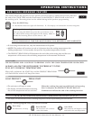
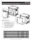
4. Remove any existing legs or casters from both of
the rotisseries.
5. Review “stacking combinations & installation
requirements” above, then attach support brackets
and legs or casters to the rotisseries intended to be
on the bottom with 1" (25mm) screws, washers, and
lock washers.
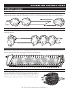
6. Punch out the knock out holes A, B, C, & D.
7. Detach decorative exhaust by removing 6 screws from
top panel of rotisserie intended to be on the bottom.
8. Remove 4 plugs (E) from top panel of rotisserie
intended to be on the bottom.
9. Apply high temp silicone around perimeter of
exhaust opening on the top panel of the rotisserie to
be on bottom (F).
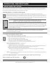
10. Carefully lift and place the upper unit into position
aligning on the bottom unit.
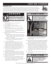
11. Secure units together by inserting a hex head screw
and a flat washer in each hold of the top unit and a
flat washer, lock washer, and hex nut inside the
bottom unit. Securely tighten all four screws.
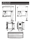
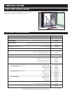
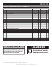
S TA C K IN G C OM B IN AT IO N S & IN S TA LL AT IO N R EQ U IR E M EN T S
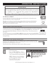
STACKING COMBINATIONS (FACTORY INSTALLED)
AR-7E rotisserie over AR-7E rotisserie
Requires 6" (152mm) leg assembly 5001414 or 5" (127mm) casters 4007 and stacking assembly
(5009 981,
5009982, 5009983, 5010355, 5010356, or 5010357 - depending on voltage and door swing - see pg 8)
for
applications within the United States. Applications outside the U.S. requires 6" (152mm) legs with
flanged feet 5001761 bolted to the floor.
[OVERALL HEIGHT: 76-7/8" (1953mm)]
A
R-7E rotisserie over AR-7H companion holding cabinet
Requires 6" (152mm) leg assembly 5001414 or 5" (127mm) casters 4007 and stacking assembly (50087 87,
5008948 or 5008922 - depending on voltage - see pg 8) for applications within the United States.
Applications outside the U.S. requires 6" (152mm) legs with flanged feet 5001761 bolted to the floor.
[
OVERALL HEIGHT: 76-7/8" (1953mm)]
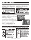
C A U T I O N
STACKING APPLICATIONS
OUTSIDE THE U.S. REQUIRE
FLANGED FEET AND MUST
BE BOLTED TO THE FLOOR.
C A U T I O N
MAKE CERTAIN TO FASTEN
EACH OF THE FOUR HOLES
I N S TA L L AT I O N
AR-7E Rotisserie Operation & Care Manual • 6